
Establishing fluidic connections between chromatography components

a technology of fluid connection and chromatography, applied in the direction of instruments, lighting and heating apparatus, separation processes, etc., can solve the problems of leakage and/or failure, dead volume of fittings, reliability and seal characteristics of conventional fittings, etc., and achieve the effect of quick and highly repeatable connection

Active Publication Date: 2015-11-12
WATERS TECH CORP
View PDF2 Cites 8 Cited by
  • Summary
  • Abstract
  • Description
  • Claims
  • Application Information

AI Technical Summary

Benefits of technology

The patent describes apparatus for connecting chromatography components without using hand tools or ferrules. The connections are made with a fluid tight connection that doesn't require torque, making them repeatable and easy to establish. This requires less mechanical force and ensures that the connections are properly established. These configurations also help to prevent carry-over, dispersion, and dead volume.

Problems solved by technology

Temperature can influence the results of the analysis, affecting such properties as the separation performance of the column and the viscosity of a mobile phase.
This can be time consuming, cumbersome (e.g., in cases in which multiple turns are required), and may lead to leaks and / or failure if the fittings are not threaded together properly and / or if adequate torque is not applied when the connection is made.
As a result, the reliability and seal characteristics of conventional fittings are becoming problematic.
As the pressure is raised and the system internal fluid volume is reduced the fitting dead volume and sensitivity to the assemblers skill become impediments to chromatographic quality.
In this regard, establishing fluid tight connections with such conventional fittings can require the use of skilled labor since it is often the case that a high degree of precision is required to ensure the connection is not only fluid tight, but is also devoid of undesirable dead volume which can lead to lost precision in the measured data.

Method used


Image

  • Establishing fluidic connections between chromatography components
  • Establishing fluidic connections between chromatography components
  • Establishing fluidic connections between chromatography components

Examples


Embodiment Construction

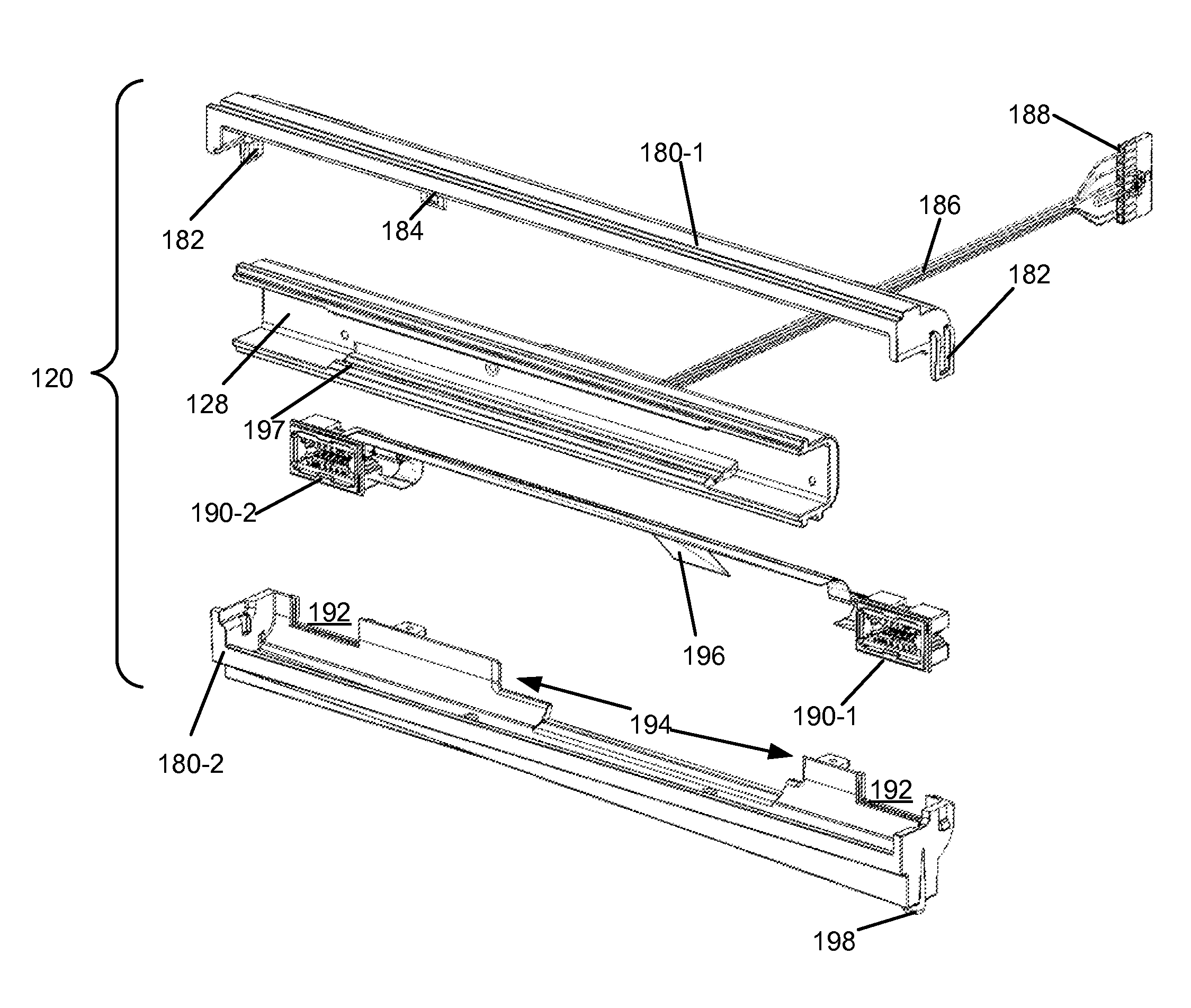
[0051]Systems described herein include apparatus for connecting fluidic tubing to a chromatography column to establish a fluid tight connection therebetween. The apparatus can provide a quick and highly repeatable fluid tight connection that does not require highly skilled operators to ensure that the connection is properly established. The apparatus allows for chromatography components, such as columns, guards, filters, tubing, etc., to be connected without the use of tools or ferrules and in such a way as to inhibit carry-over, dispersion, and dead volume. Various implementations of these systems relate to liquid-chromatography apparatus, for example, HPLC (High Performance Liquid Chromatography) and UPLC (Ultra Performance Liquid Chromatography) systems.

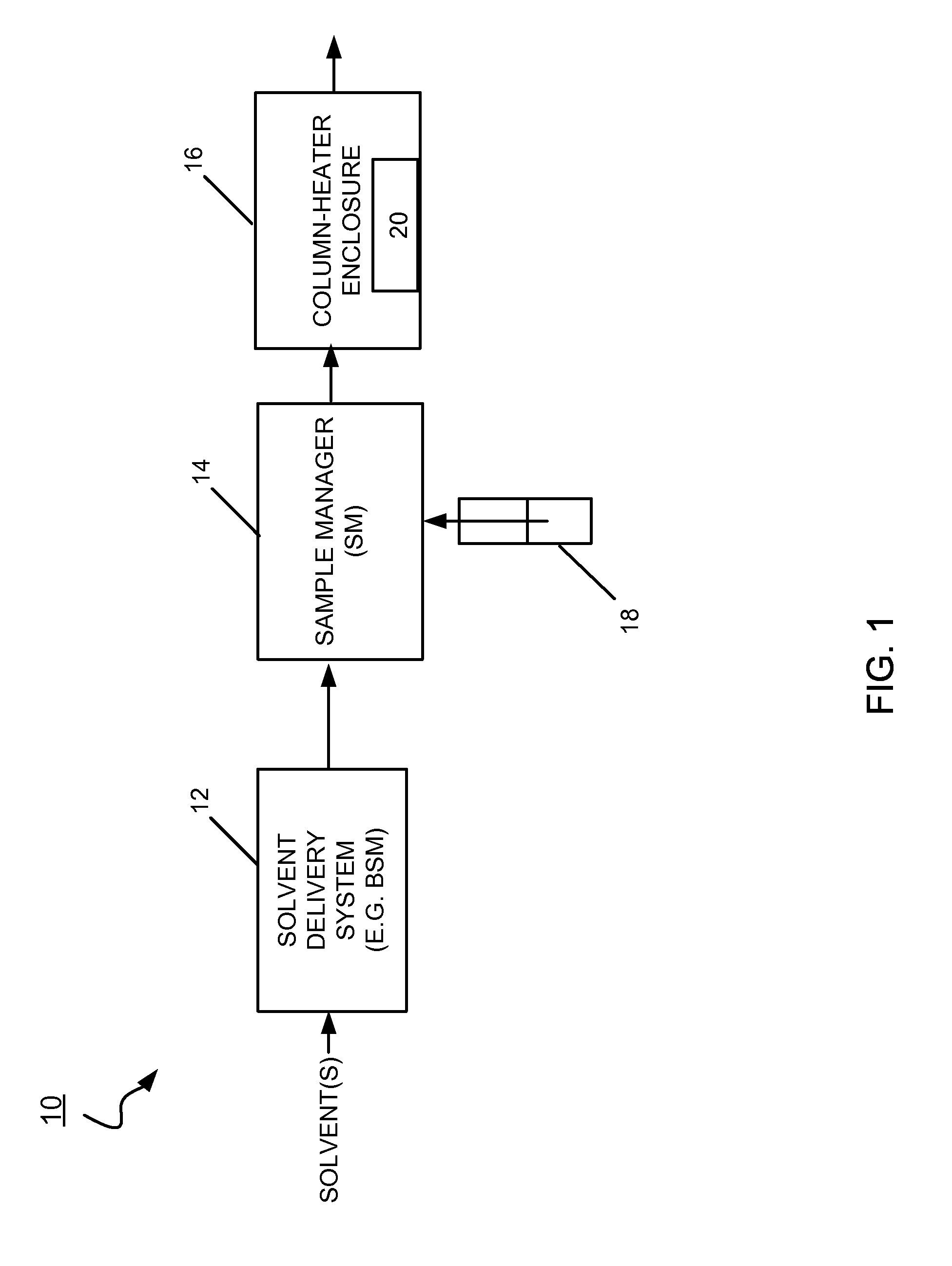
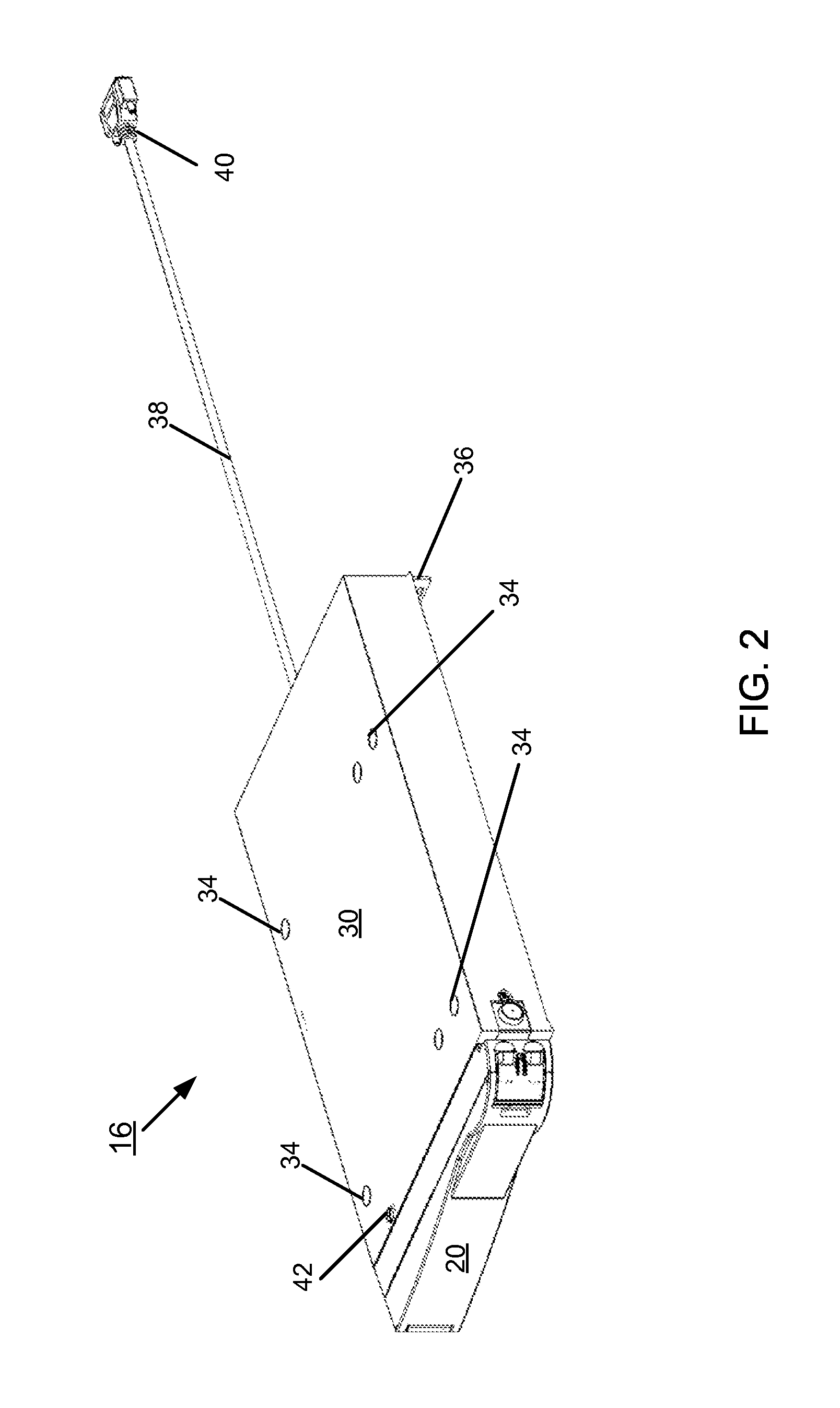
[0052]FIG. 1 shows an implementation of a liquid chromatography system 10 for separating a sample into its constituents. The liquid chromatography system 10 includes a solvent delivery system 12 in fluidic communication with a sam...


PUM

PropertyMeasurementUnit
Temperatureaaaaaaaaaa
Forceaaaaaaaaaa
Diameteraaaaaaaaaa

Abstract

A clamp assembly includes a rail configured to receive a first fluidic assembly, and a carriage slidably mounted to the rail and configured to receive a second fluidic assembly. The carriage is operable to establish a first fluid tight seal between the first fluidic assembly and a chromatography column received within the clamp assembly, and to establish a second fluid tight seal between the second fluidic assembly and the chromatography column.

Description

RELATED APPLICATIONS[0001]This application claims priority to and benefit of U.S. Provisional Patent Application No. 61 / 578,257, entitled “Establishing Fluidic Connections between Chromatography Components,” filed Dec. 21, 2011, which is incorporated by reference herein in its entirety.TECHNICAL FIELD[0002]This disclosure relates to establishing fluidic connections between chromatography components.BACKGROUND[0003]Chromatography is a set of techniques for separating a mixture into its constituents. Generally, in a liquid chromatography analysis, a pump system takes in and delivers a mixture of liquid solvents (and / or other fluids) to a sample manager, where a sample awaits injection into the solvents. The sample is the material under analysis. Examples of samples include complex mixtures of proteins, protein precursors, protein fragments, reaction products, and other compounds, to list but a few. In an isocratic chromatography application, the composition of the liquid solvents rema...

Claims


Application Information

Patent Timeline
IPC IPC(8): G01N30/60B01D15/10G01N30/30G01N30/02F16L19/00
CPCG01N30/6026G01N30/6039G01N30/02Y10T29/53952G01N30/30B01D15/10Y10T29/53917F16L19/00G01N2030/3061G01N30/6047
Inventor KIRBY, PETERPEROZA, MARCOS O.TRUDEAU, STEVEN D.HILL, RYANFISK, RAYMOND P.BELANGER, JONATHANLEVEILLE, WADE P.
Owner WATERS TECH CORP
Learn More