Coded lock

Inactive Publication Date: 2015-11-19
YIFENG MFG
View PDF0 Cites 10 Cited by
  • Summary
  • Abstract
  • Description
  • Claims
  • Application Information

AI Technical Summary

Benefits of technology

[0017]The coded lock provided by the present invention has the advantage that: as the technical pro

Problems solved by technology

At this point, the clutch block is limited; and as the clutch block and t

Method used


Image

  • Coded lock
  • Coded lock
  • Coded lock

Examples


Example

REFERENCE NUMERALS OF THE ACCOMPANYING DRAWINGS

[0028]

 1—Housing 2—Password Wheel 3—Push Switch 4—Base Plate 5—Password Adjustment Block 6—Push Rod 7—Latch Hook 8—Movable Plate 9—Lock Core 10—Driving Rod 11—Clutch Block 12—Password Adjustment Wheel 13—Bottom Shell 61—Connecting Body 31—Pushing Portion 32—Connecting Portion 14—Elastic member321—Moving Groove111—Control Portion112—Vertical Block 62—Recess 71—Hook Portion 72—Limited Portion

DETAILED DESCRIPTION OF THE PREFERRED EMBODIMENTS

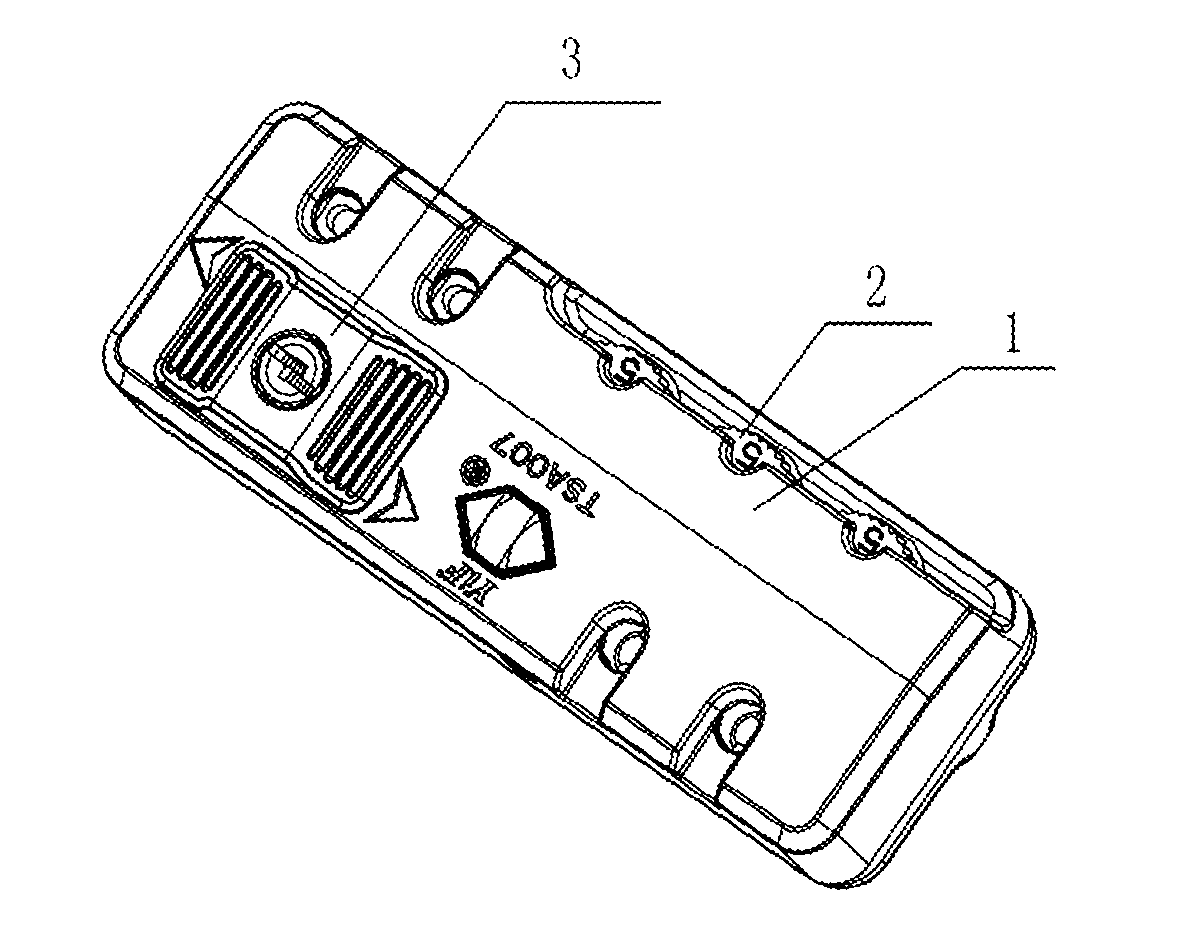
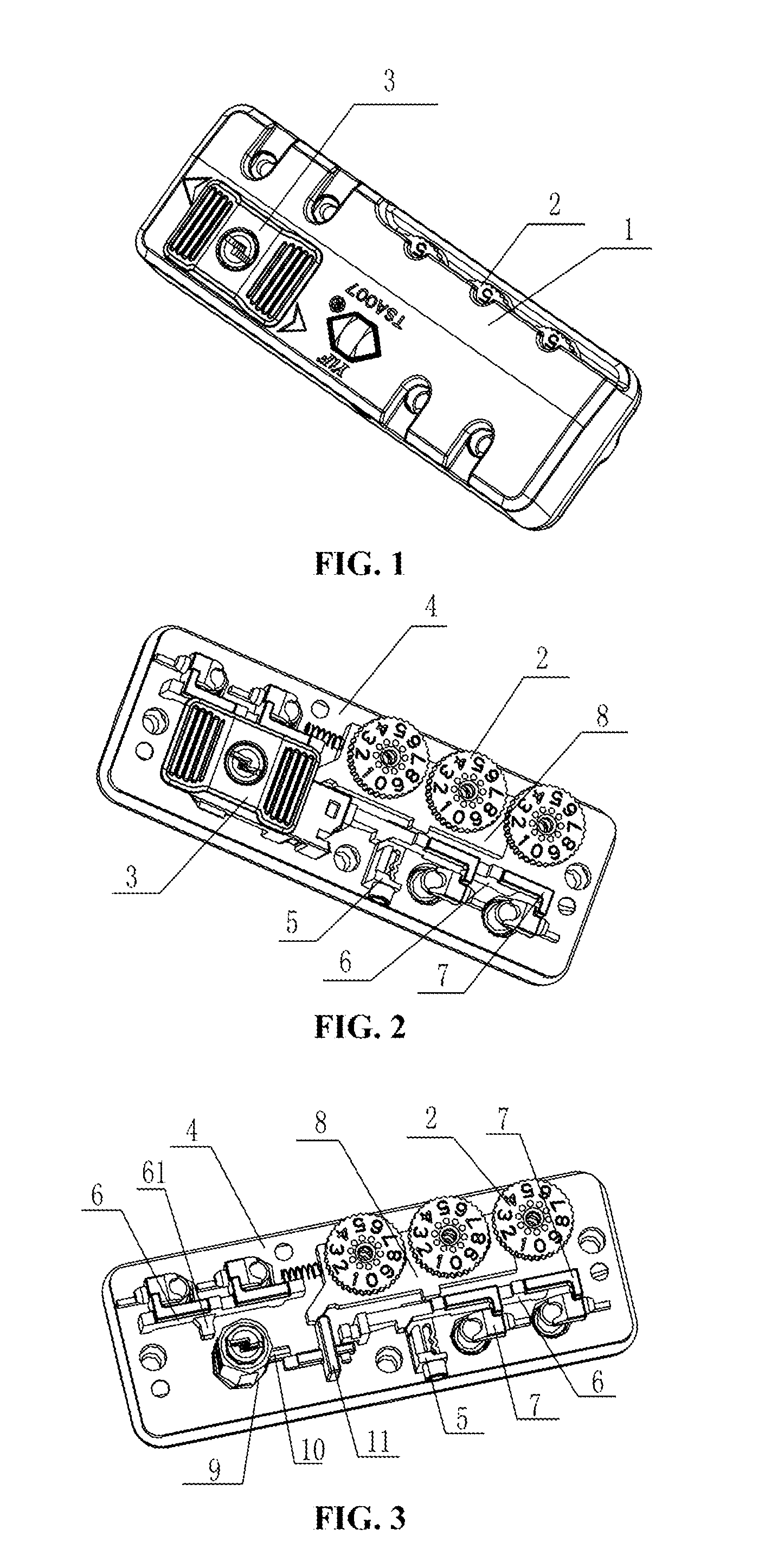
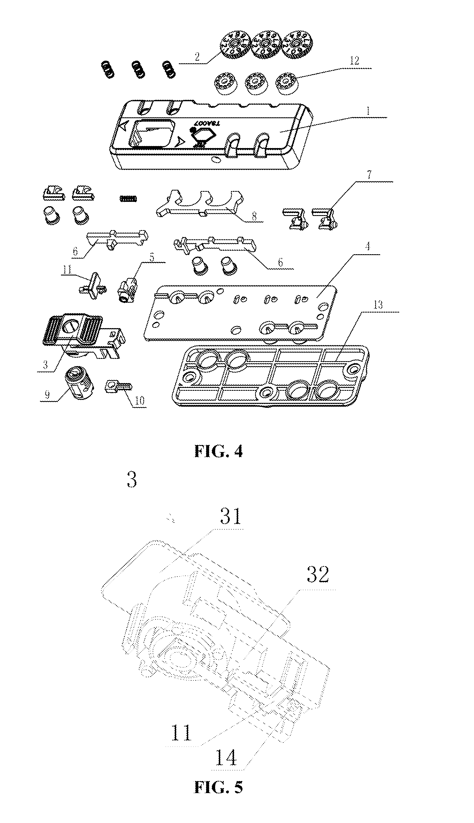
[0029]Embodiments: as shown in FIGS. 1 to 10.

[0030]The present invention relates to a coded lock, which comprises a base plate 4 and a housing 1 which are connected with each other; the base plate 4 is provided with a password mechanism, a key lock assembly and latch hook assemblies; the coded lock further comprises a clutch block 11 and a push switch 3; the push switch 3 is connected with the latch hook assemblies; the clutch block 11 is clamped with the push switch 3 and may perform longitudinal movem...


PUM


Abstract

A coded lock comprises a base plate and a housing which are fixedly connected with each other; the base plate is provided with a password mechanism, a key lock assembly and latch hook assemblies and further includes a clutch block and a push switch; the push switch is connected with the latch hook assemblies; the clutch block is clamped with the push switch and may perform longitudinal movement relative to the push switch; the key lock assembly is provided with a driving rod for driving the clutch block to perform longitudinal movement; the password mechanism is provided with a movable plate which is provided with a clamping groove clamped with the clutch block; the coded lock is provided with an elastic member for pushing the clutch block towards the clamping groove; and in the case of password unlocking, the movable plate moves and pushes the clutch block away from the clamping groove.

Description

FIELD OF THE INVENTION[0001]The present invention belongs to the technical field of mechanical locks, in particular relates to a coded lock.BACKGROUND OF THE INVENTION[0002]Coded locks are widely applied to cases and bags, e.g., zipper pulls of the cases and bags. When the coded locks are applied, due to the unreasonable structural design, the coded locks are inconvenient to use and the occupied volume is very large. For instance, in the Chinese utility model patent Appl. No. 201220744304.5, titled “zipper coded lock”, the zipper coded lock mainly adopts a left push block and a right push block to push latch hooks to move and hence controls the latch hooks on both sides to be in the locked state. When the two push blocks are adopted, the two push blocks are disposed at both ends of a housing, and hence the occupied volume can be very large. Moreover, when the zipper coded lock is used, reverse pressing is required, and hence the operation is inconvenient at all.SUMMARY OF THE INVENT...

Claims


Application Information

Patent Timeline
IPC IPC(8): E05B37/00
CPCY10T70/7147E05B37/0034E05B35/105E05B37/0031E05B37/12
Inventor LAI, LEO
Owner YIFENG MFG
Why Eureka
Try Eureka