This helps you quickly interpret patents by identifying the three key elements:
Problems solved by technology
Method used
Benefits of technology
Benefits of technology
A more specific object of the present invention is to provide a single-piece slider member for closure devices which is easily installed upon and assembled onto interlocking fastening strips.
A further object of the present invention is to provide a single-piece slider member which is convenient to use.
An additional another object of the present invention is to provide a single-piece slider member of the foregoing type which is relatively simple and economical in construction, and which lends itself to reliable operation and use.
Accordingly, a single-piece slider member is provided for use with a closure device having interlocking fastening strips disposed along opposing side walls of a storage container, such as a conventional plastic bag. The slider member comprises a main body portion which is adapted to be installed upon the interlocking fastening strips and a door portion which is hingedly attached to the main body portion along a hinge portion for movement between open and closed positions. When the main body portion of the slider member is installed upon the interlocking fastening strips, the hinge portion is substantially perpendicular thereto. The slider member is also provided with a latching mechanism which conveniently retains each of the door portions in the closed position. During assembly, the main body portion of the slider member is installed upon the interlocking fastening strips and then each door portion is moved into the closed position to slidably attach the slider member onto the interlocking fastening strips in a self-retaining manner.
Problems solved by technology
With such closure devices, however, it is often difficult to determine whether the fastening strips are fully, occluded.
This problem is particularly acute when the fastening strips are relatively narrow.
Such fastening strips are particularly difficult to manipulate or handle by individuals with limited manual dexterity.
While the use of a slider certainly facilitates the opening and closing of fastening strips, there are certain difficulties involved with installing and assembling the slider onto the fastening strips and with retaining the slider thereon.
Such single-piece sliders, however, suffer from assorted deficiencies including, for example, a relatively complex construction, a high relative cost, and a design which lends itself to difficult installation upon and assembly onto the fastening strips.
Method used
Image
Click on the blue label to locate the original text in one second.
Reading with bidirectional positioning of images and text.
Examples
first embodiment
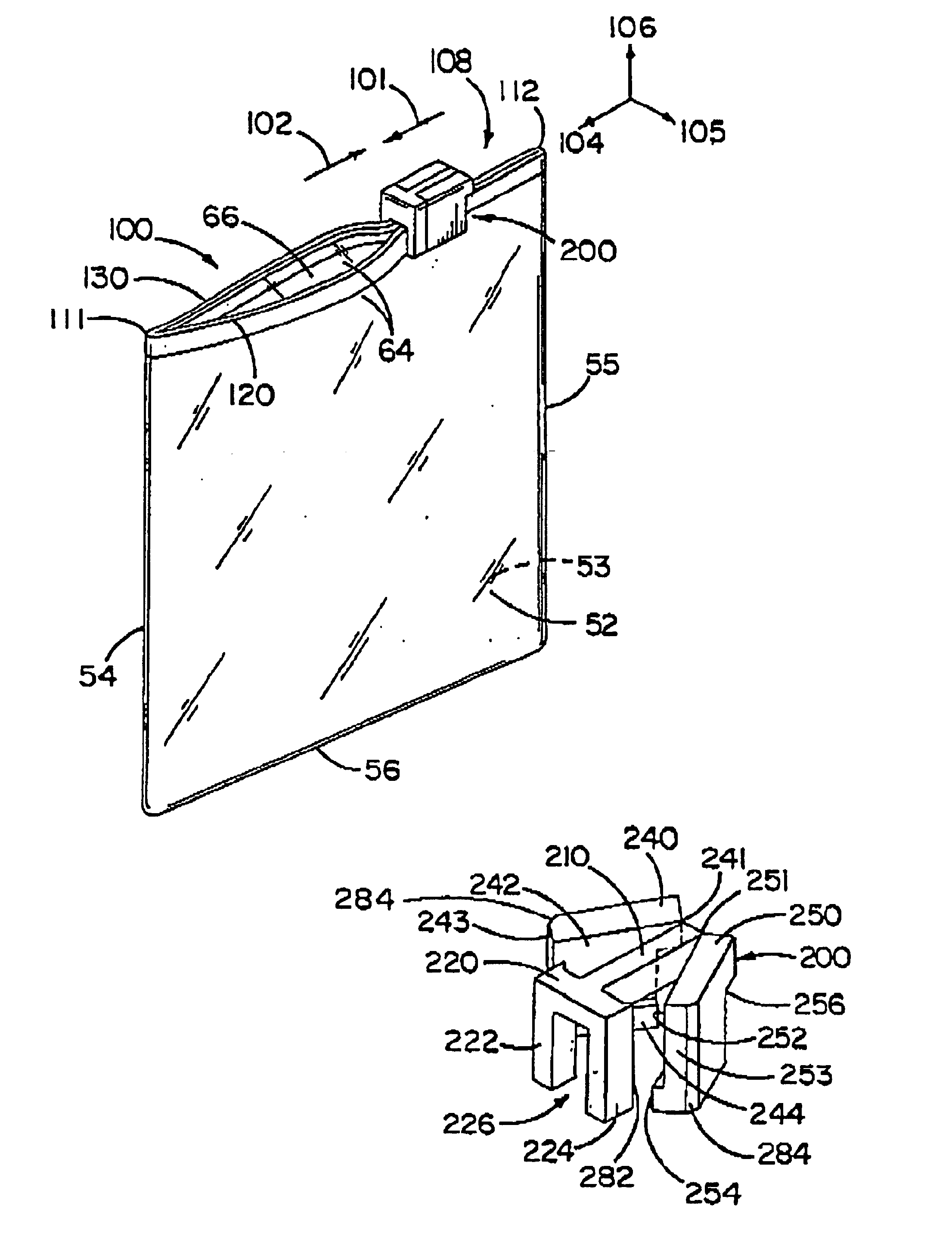
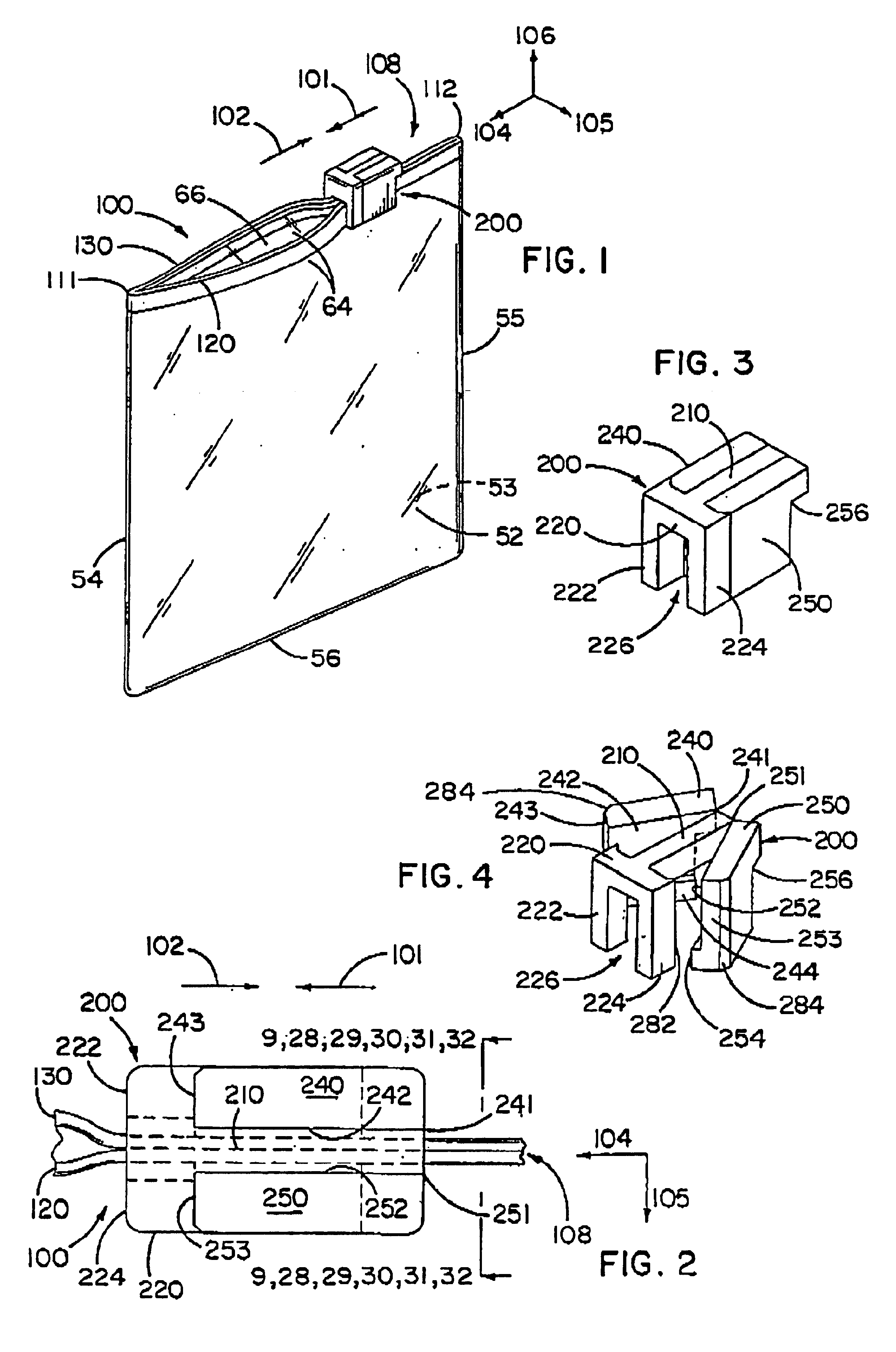
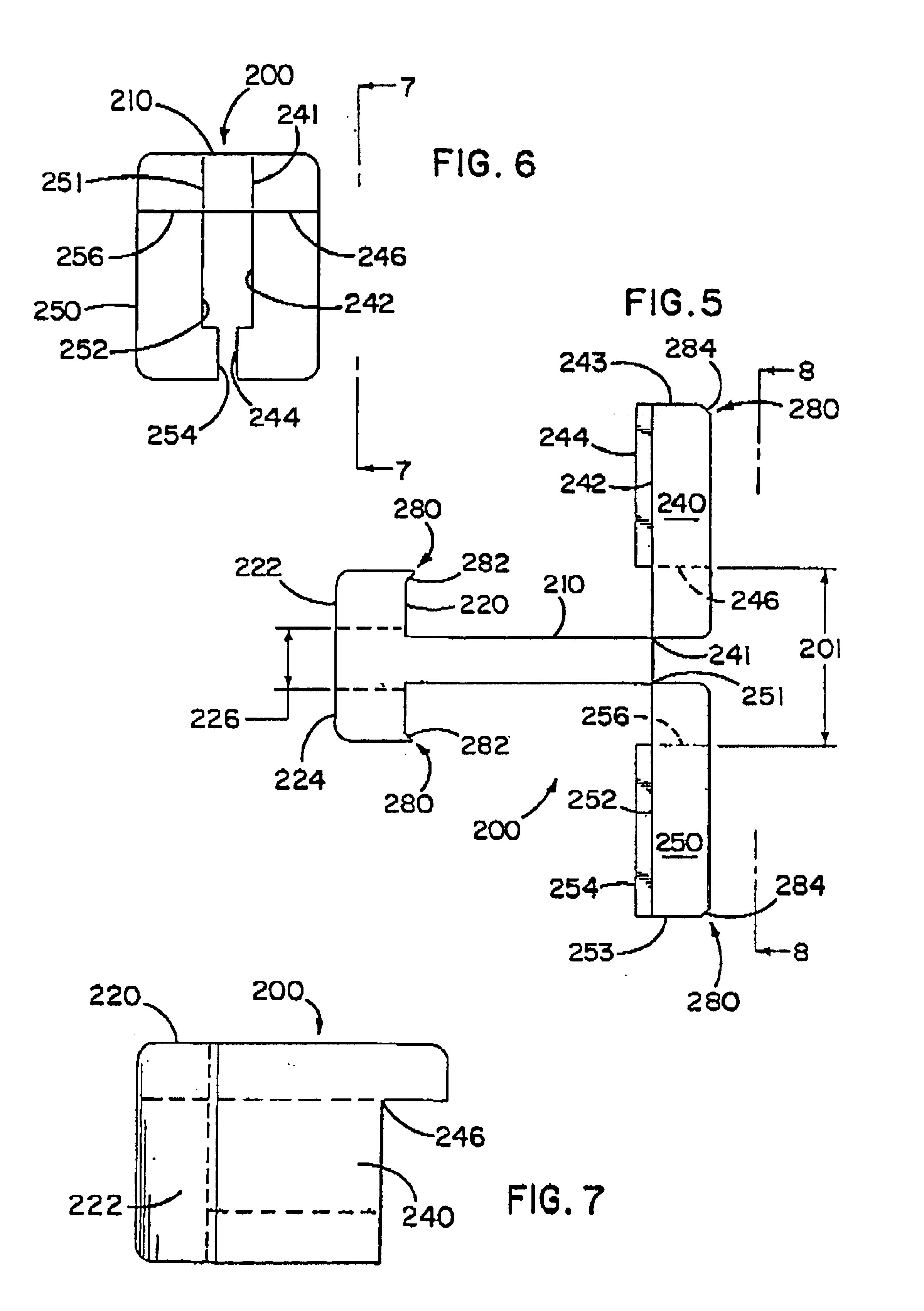
As shown in FIGS. 1-9, the slider member 200 includes a main body portion 210 which is adapted to be positioned upon and installed along the interlocking fastening strips 108. The main body portion 210 of the slider member 200 further includes a transverse body segment or saddle 220 which is provided with a pair of spaced-apart and downwardly extending side members 222 and 224 with a slot or opening 226 therebetween. The main body portion 210 and the transverse body segment 220 have a generally T-shaped configuration when viewed from above, as shown in FIGS. 1-5. The transverse body segment 220 has an inverted U-shaped configuration when viewed from the front, as shown in FIGS. 3 and 4.
The slider member 200 is also provided with a pair of door portions 240 and 250 which are integrally hingedly attached to opposite sides of the main body portion 210 along respective hinge portions 241 and 251. The two door portions 240 and 250 each have a first side surface 242 and 252, respectively,...
second embodiment
the inventive slider member 300 is shown in FIGS. 10-14. Like the first embodiment of, the slider member 200, the second embodiment of the slider member 300 includes a main body portion 310 which is adapted to be positioned upon and installed along the interlocking fastening strips 308. The main body portion 310 of the slider member 300 also includes a pair of transverse body segments or saddles 320 and 330 which are formed on opposite ends thereof and are arranged substantially perpendicular thereto. More specifically, the first transverse body segment 320 includes a pair of downwardly extending side members 322 and 324 with a slot or opening 326 therebetween. Similarly, the second transverse body segment 330 also includes a pair of downwardly extending side members 332 and 334 with a slot or opening 336 therebetween on account of this construction, the main body portion 310 and the two transverse body segments 320 and 330 of slider member 300 have a generally H-shaped configuratio...
third embodiment
the inventive slider member 400 is shown in FIG. 15. The third embodiment of the slider member 400 includes a main body portion 410 which is adapted to be positioned upon and installed along the fastening strips 408. The slider member 400 also includes two pairs of opposed door portions 440, 450, 460, and 470 which are integrally hingedly attached to opposite outer corners of the main body portion 410 along respective hinge portions or living hinge structures 441, 451, 461, and 471. The four door portions 440, 450, 460, and 470 each have a first side surface 442, 452, 462, and 472, respectively, a second side surface 443, 453, 463, and 473, respectively, and a shoulder 444, 454, 464, and 474, respectively. The shoulders 444, 454, 464, and 474 are formed on a lower-end of the first side surface 442, 452, 462, and 472. On account of this construction, the main body portion 410 has a generally linear configuration when viewed from above, as shown in FIG. 15. Also, the slider member 400...
PUM
Abstract
A single-piece slider member (200) is provided for use with a closure device having interlocking fastening strips (108) disposed along opposing side walls (52, 53) of a storage container, such as a conventional plastic bag. The slider member (200) comprises a main body portion (210) which is adapted to be installed upon the interlocking fastening strips (108) and a door portion (240) which is hingedly attached to the main body portion (210) along a hinge portion (241) for movement between open and closed positions. When the main body portion (210) is installed upon the fastening strips (108), the hinge portion (241) is substantially perpendicular to the main body portion (210). The slider member (200) is also provided with a latching mechanism (280) which retains the door portion (240) in the closed position. During assembly, the main body portion (210) of the slider member (200) is installed upon the interlocking fastening strips (108) and then the door portion (240) is moved into the closed position to slidably attach the slider member (200) onto the interlocking fastening strips (108).
Description
FIELD OF THE INVENTIONThe present invention relates generally to closure devices and, more particularly, to a closure device comprised of interlocking fastening strips and a slider member. The inventive closure device may be employed in traditional fastener areas and is particularly well suited for fastening flexible storage containers, such as plastic bags.BACKGROUND OF THE INVENTIONThe use of closure devices for fastening storage containers, including plastic bags, is generally well known. Furthermore, the manufacture of closure devices made of plastic materials is generally well known to those skilled in the art, as demonstrated by the numerous patents in this area.A particularly well-known use for closure devices is in connection with flexible storage containers, such as plastic bags. Such closure devices provide a convenient way to close the bag in order to retain matter therein.Conventional closure devices typically utilize mating fastening strips or closure elements which are...
Claims
Application Information
Patent Timeline
Application Date:The date an application was filed.
Publication Date:The date a patent or application was officially published.
First Publication Date:The earliest publication date of a patent with the same application number.
Issue Date:Publication date of the patent grant document.
PCT Entry Date:The Entry date of PCT National Phase.
Estimated Expiry Date:The statutory expiry date of a patent right according to the Patent Law, and it is the longest term of protection that the patent right can achieve without the termination of the patent right due to other reasons(Term extension factor has been taken into account ).
Invalid Date:Actual expiry date is based on effective date or publication date of legal transaction data of invalid patent.

