Unlock instant, AI-driven research and patent intelligence for your innovation.

Liquid ejection head, method for cleaning the head, recording apparatus provided with the head

Active Publication Date: 2015-11-26
CANON KK
View PDF3 Cites 7 Cited by
  • Summary
  • Abstract
  • Description
  • Claims
  • Application Information

AI Technical Summary

Benefits of technology

This patent describes a liquid ejection head used in recording devices. The head has conductivity measuring units to detect impurities in the liquid and an insulating protective layer to prevent them from sticking to the heating portion of the head. The head also has an upper electrode made of a material that reacts with the liquid to be ejected. The patent also describes a method for cleaning the head using an electrochemical reaction to remove impurities and a recording apparatus that includes the cleaned head for recording. The technical effects of the invention include improving the quality of liquid ejection and reducing impurities in the liquid.

Problems solved by technology

A heat generating portion of the electrothermal converting element is exposed to high temperatures and, at the same time, is complexly subject to cavitation impacts caused by foaming and contraction of a liquid, and chemical actions caused by ink.
A coloring material, an additive, and other materials included in the ink are separated with a molecular level when heated at high temperatures, and these materials change to hardly soluble materials called “kogation.” When the kogation is physically adsorbed onto the upper protective layer, the following problems occur: heat is conducted unevenly from the heat generating resistive element to the ink, and, therefore, ejection speed of the ink is lowered, foaming becomes unstable, and more energy is required for the ejection.

Method used


Image

  • Liquid ejection head, method for cleaning the head, recording apparatus provided with the head
  • Liquid ejection head, method for cleaning the head, recording apparatus provided with the head
  • Liquid ejection head, method for cleaning the head, recording apparatus provided with the head

Examples


example 1

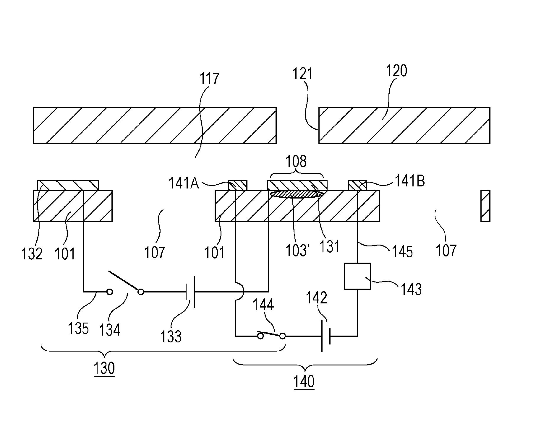
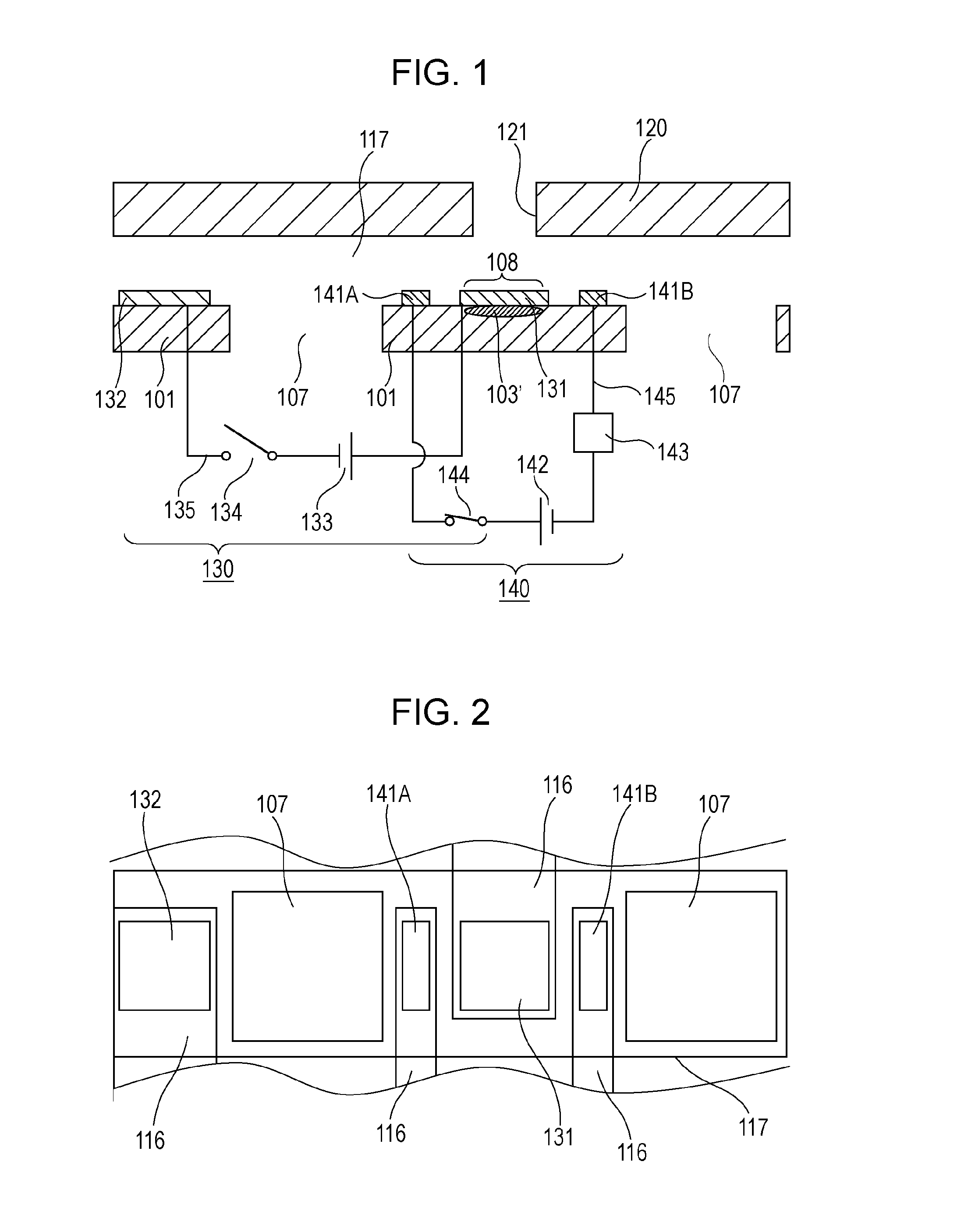
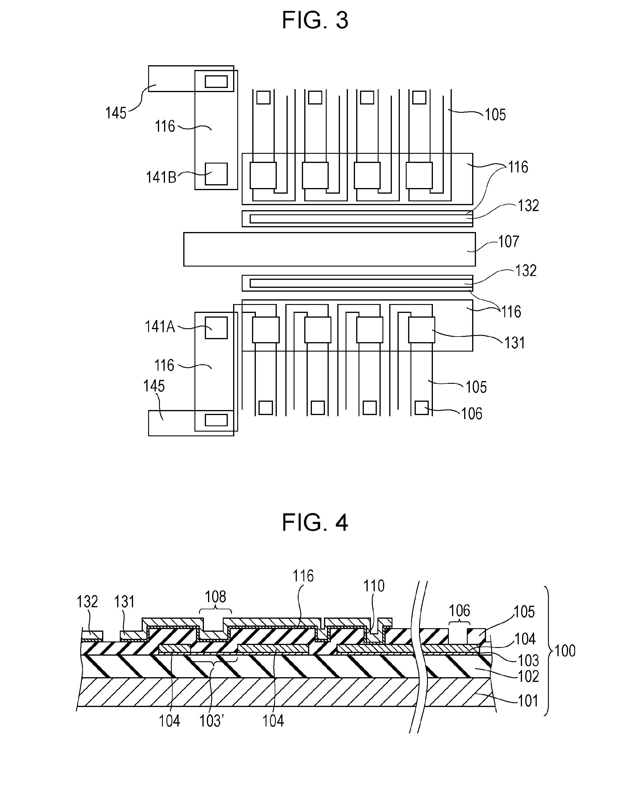
[0071]As a liquid ejection head of Example 1, in the same manner as that of the method disclosed in Japanese Patent Laid-Open No. 2008-105364, as illustrated in FIG. 2 (or FIG. 3), an SiO2 heat accumulation layer, a TaSiN heat generating resistive element layer 103, an Al wiring layer 104, and an SiN protective layer 105 are formed in this order on an Si substrate 101. The electrothermal converting portion 103′ is formed by etching a part of the Al wiring layer 104. After forming 100 nm of tantalum as the adhesion layer 116 on the protective layer 105, 50 nm of an iridium film is formed. The iridium film is patterned to form the upper electrode 131, the counter electrode 132, and the electrode pair 141A and 141B. Then, in the same manner as disclosed in Japanese Patent Laid-Open No. 2008-105364, the ink supply port 107 is formed, the flow path forming member 120 is formed, other necessary terminal portions are formed, and the like. The liquid ejection head is thus completed. The hea...

example 2

[0078]A liquid ejection head that supports a plurality of colors is manufactured in the same manner as in Example 1. Using this liquid ejection head, an experiment of removal of kogation is conducted. Dye magenta ink is used in a nozzle array that performs ejection and removal of kogation, and dye cyan ink is used in a nozzle array adjacent to the above nozzle array. Each of the electrodes for conductivity measurement in Example 2 is disposed between the upper electrode 131 above the heat generating portion and the liquid supply port 107 as illustrated in FIG. 2.

[0079]First, magenta ink is used and the electrothermal converting portion 103′ is driven under predetermined conditions so that kogation K is deposited on the surface of the thermal action portion 108. When a surface state is observed, kogation K is deposited substantially uniformly on the surface of the thermal action portion 108. When recording is performed using the liquid ejection head in this state, it is examined that...


PUM


Abstract

Cleaning under appropriate cleaning conditions is performed by disposing an electrode pair for measuring conductivity in the same liquid chamber as that of a material layer (i.e., an upper electrode) of a surface of a thermal action portion to be eluted, and measuring conductivity of a liquid using the electrode pair before kogation is removed.

Description

BACKGROUND OF THE INVENTION[0001]1. Field of the Invention[0002]The present invention relates to a liquid ejection head that ejects ink by a liquid ejecting method and records on a recording medium, and a method for cleaning the head. The invention relates also to a recording apparatus provided with the head.[0003]2. Description of the Related Art[0004]In a liquid ejecting method (i.e., an inkjet recording method), a liquid (e.g., ink) is ejected from ejection ports provided in a liquid ejection head, and is caused to adhere for recording on a recording material, such as a paper sheet. The inkjet recording method in which the liquid is ejected by foaming of the liquid produced by thermal energy generated by electrothermal converting elements enables high quality and high speed printing.[0005]Typically, a liquid ejection head of this kind has a plurality of ejection ports, a flow path communicating with the ejection ports, and a plurality of electrothermal converting elements that ge...

Claims


Application Information

Patent Timeline
IPC IPC(8): B41J2/165
CPCB41J2002/16564B41J2/16517B41J2/04508B41J2/0451B41J2/04555B41J2/0458B41J2/14072B41J2/14153B41J2/16508B41J2/16523B41J2/16532B41J2002/14354
Inventor KATO, MAKIMATSUI, TAKAHIROSAITO, ICHIROISHIDA, YUZURUTAKAHASHI, KENJIYOSHINARI, NORIHIROMISUMI, YOSHINORI
Owner CANON KK
Features
  • R&D
  • Intellectual Property
  • Life Sciences
  • Materials
  • Tech Scout
  • Unparalleled Data Quality
  • Higher Quality Content
  • 60% Fewer Hallucinations
Learn More