Aircraft and method of managing evaporated cryogenic fuel

a technology of cryogenic fuel and aircraft, applied in the field of aircraft systems, can solve the problem of low engine system efficiency

Active Publication Date: 2015-12-03
GENERAL ELECTRIC CO
View PDF7 Cites 7 Cited by
  • Summary
  • Abstract
  • Description
  • Claims
  • Application Information

AI Technical Summary

Problems solved by technology

Use of compressor air for cooling may

Method used


Image

  • Aircraft and method of managing evaporated cryogenic fuel
  • Aircraft and method of managing evaporated cryogenic fuel
  • Aircraft and method of managing evaporated cryogenic fuel

Examples


Embodiment Construction

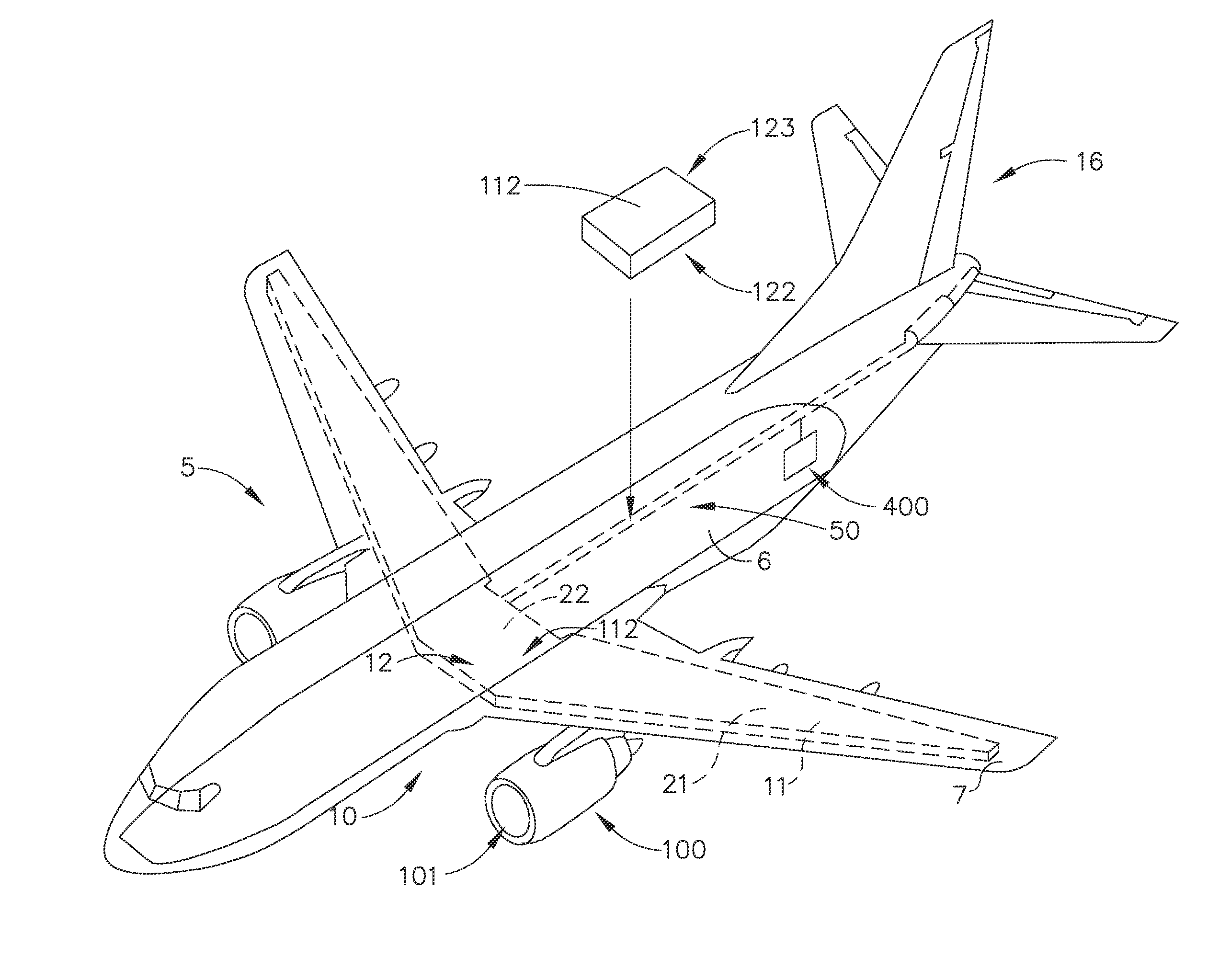
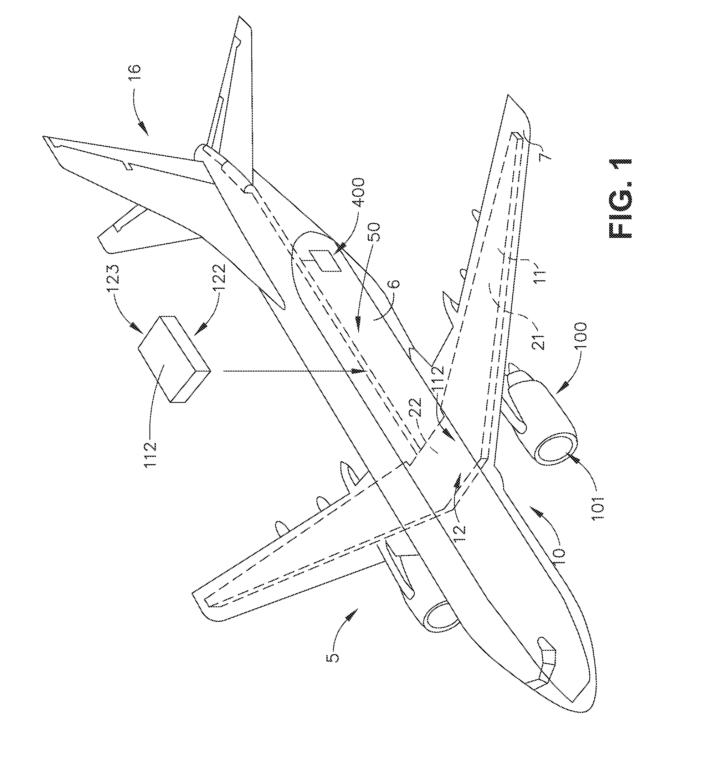
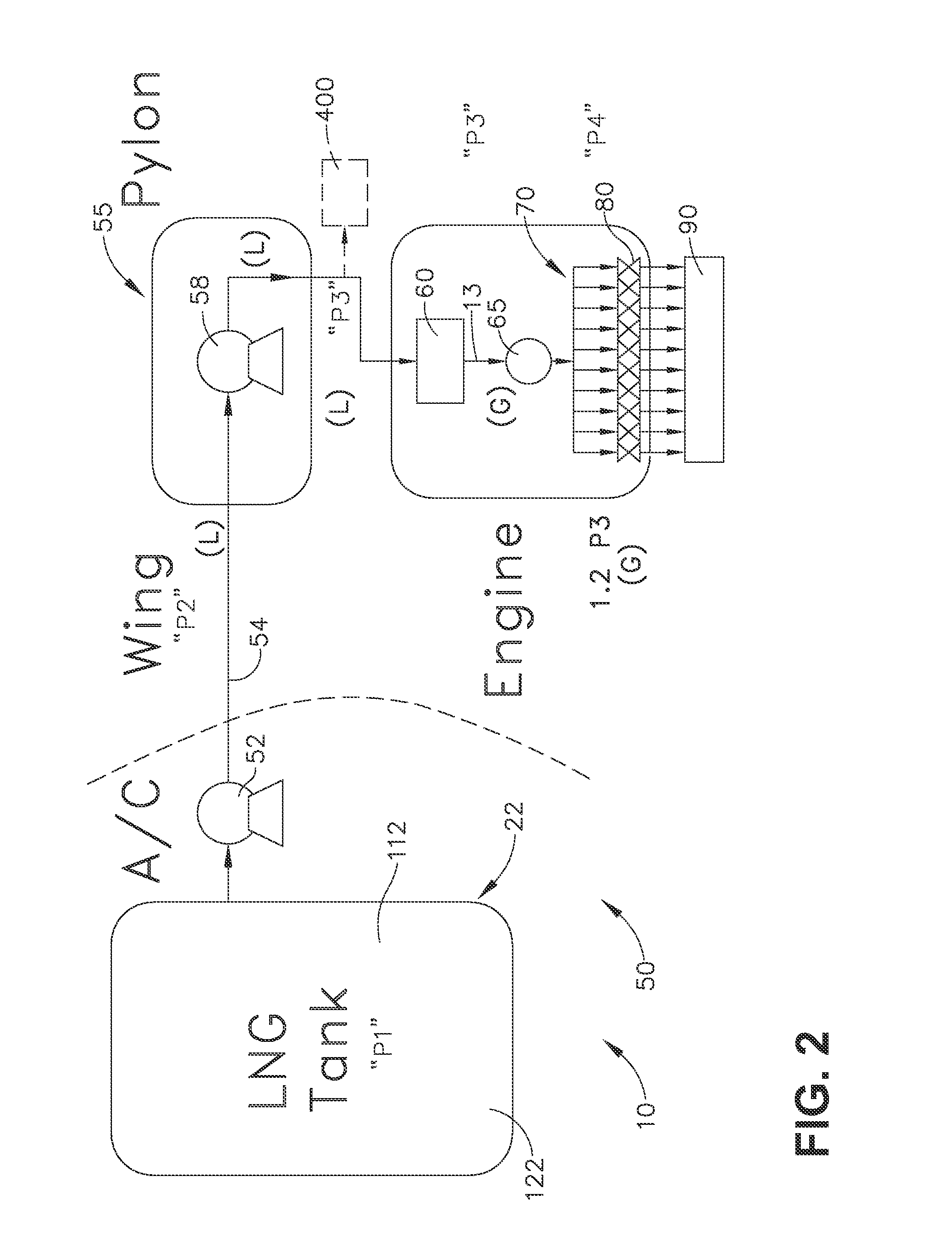
[0005]In one aspect, an embodiment of the invention relates to an aircraft having at least one turbine engine providing propulsive force for the aircraft and a cryogenic fuel system including a passively cooled cryogenic fuel storage tank located within the aircraft, a pressure vent fluidly coupled to the cryogenic fuel storage tank and exhausting evaporated gas from the cryogenic fuel to define a natural gas vent stream, and a catalytic converter fluidly coupled to the pressure vent and receiving the natural gas vent stream and converting the natural gas vent stream into a second gas stream comprising the products of oxidation.

[0006]In another aspect, an embodiment of the invention relates to a method of managing evaporated cryogenic fuel in a storage tank of a cryogenic fuel system of an aircraft, including venting gas in the form of evaporated cryogenic fuel from the storage tank to maintain an internal pressure in the storage tank, mixing the vented gas with air to form a vented...


PUM


Abstract

A method of managing evaporated cryogenic fuel in a storage tank of a cryogenic fuel system of an aircraft and an aircraft having at least one turbine engine providing propulsive force for the aircraft and a cryogenic fuel system including a passively cooled cryogenic fuel storage tank located within the aircraft, a pressure vent fluidly coupled to the cryogenic fuel storage tank and exhausting evaporated gas from the cryogenic fuel to define a natural gas vent stream, and a catalytic converter fluidly coupled to the pressure vent.

Description

CROSS-REFERENCE TO RELATED APPLICATIONS[0001]This is a national stage application under 35 U.S.C. §371(c) of prior-filed, co-pending, PCT application serial number PCT / US2013 / 071806, filed on Nov. 26, 2013, which claims priority to U.S. Provisional Patent Application No. 61 / 746,953, filed on Dec. 28, 2012, These applications are incorporated herein in their entirety.BACKGROUND OF THE INVENTION[0002]The technology described herein relates generally to aircraft systems, and more specifically to aircraft systems using dual fuels in an aviation gas turbine engine and a method of operating same.[0003]Certain cryogenic fuels such as liquefied natural gas (LNG) may be cheaper than conventional jet fuels. Current approaches to cooling in conventional gas turbine applications use compressed air or conventional liquid fuel. Use of compressor air for cooling may lower efficiency of the engine system.[0004]Accordingly, it would be desirable to have aircraft systems using dual fuels in an aviati...

Claims


Application Information

Patent Timeline
IPC IPC(8): B64D37/30B64D37/02
CPCB64D37/02B64D37/30Y02T50/40Y02T90/40
Inventor EPSTEIN, MICHAEL JAYDELGADO, JR., ADONWEISGERBER, ROBERT HAROLD
Owner GENERAL ELECTRIC CO
Why Eureka
Try Eureka