Dental membrane or tissue placement forceps

Active Publication Date: 2015-12-10
FULKERSON BRAD
View PDF17 Cites 3 Cited by
  • Summary
  • Abstract
  • Description
  • Claims
  • Application Information

AI Technical Summary

Benefits of technology

[0007]In one aspect, the invention pertains to a forceps especially designed for placing membranes for regenerative osseous surgery in dentistry, or placing other flat, flexible materials during dental or oral surgery procedures such as connective tissue grafts. When used for placing membranes in regenerative osseous surgery, the forceps includes a pair of forceps arms with a forceps tip on one of the arms and a thin, spatula located on the other arm. The membrane is held between the forceps tip and the inward face of the spatula when the arms are pushed together to a closed position. The spatula is oriented substantially perpendicular to the direction in which the opposing tip and spatula move inward toward one another to grip the membrane (i.e. substantially perpendicular to the gripping plane). The inward spatula face is concave in one direction and forms a trough for the membrane juxtaposed the opposing tip. Desirably, the deepest region of the

Problems solved by technology

Sometimes the space in which the membrane must be placed is quite narrow, which often causes ideal placement to be difficult.
Similarly, as flapless and less invasive approaches are becoming more widely advocated, so is this issue of

Method used


Image

  • Dental membrane or tissue placement forceps
  • Dental membrane or tissue placement forceps
  • Dental membrane or tissue placement forceps

Examples


Example

DETAILED DESCRIPTION OF THE DRAWINGS

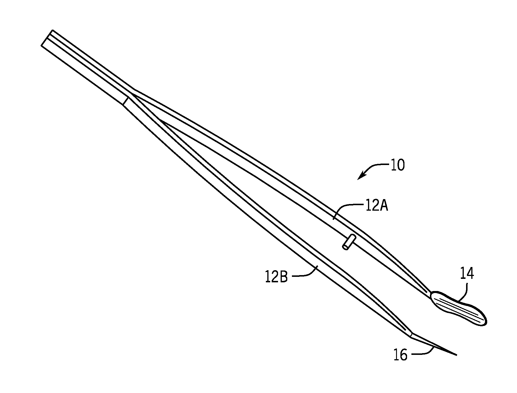
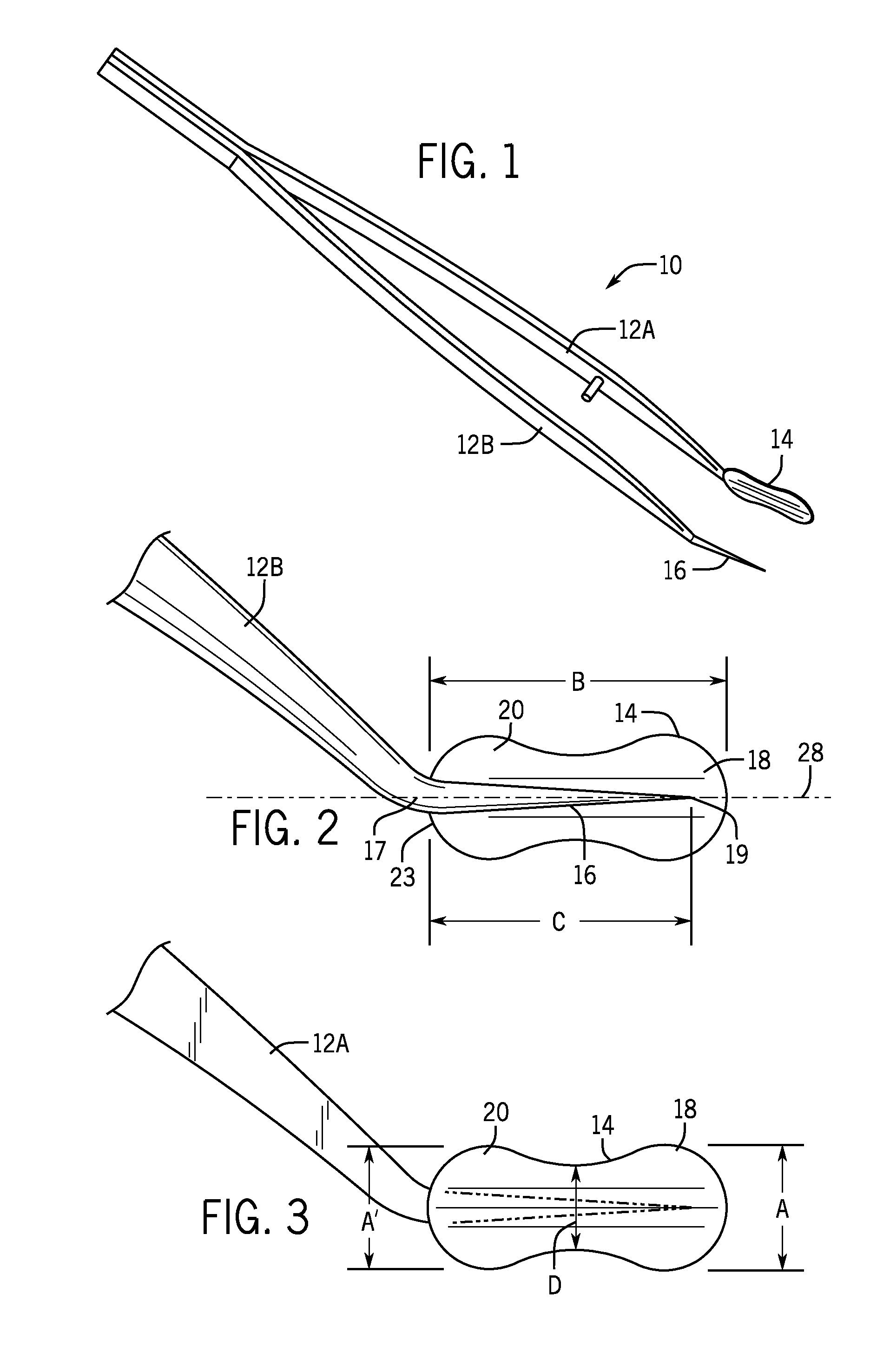
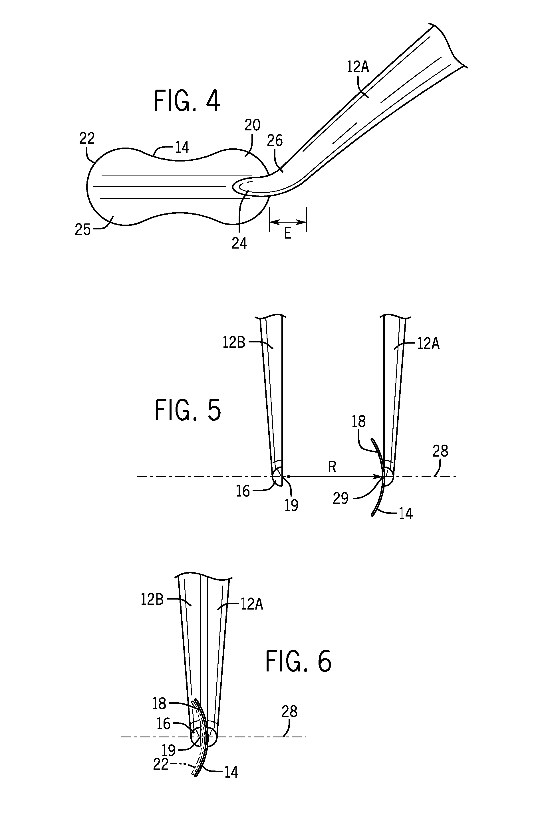
[0019]FIGS. 1 through 6 illustrate a membrane placement forceps 10 constructed in accordance with a first embodiment of the invention. The forceps 10 is held in the hand of the surgeon and includes opposing arms 12A and 12B. A broad, thin spatula 14 is located at the distal end of forceps arm 12A to provide maximum contact with the membrane 22 (FIG. 6) during insertion or placement over a dental graft site. The tip 16 on the opposing arm 12B is the same or similar to a conventional forceps tip. While FIG. 1 shows a forceps having standard forceps arms 12A, 12B, the spatula 14 can be implemented on other types of forceps. For example, a scissors style forceps can be used in accordance with the invention and may provide for easier withdrawal of the forceps after placement into tight spaces. In use, the membrane 22, FIG. 6, is cut to match the dimensions of the spatula 14, e.g. using the spatula 14 as a template. Then, the membrane 22 is gripped betw...


PUM


Abstract

A dental membrane placement forceps which includes a thin spatula on the tip of one arm of the forceps. The spatula has a concave inward face juxtaposed the tip on the opposing forceps arm and is oriented substantially perpendicular to the direction in which the opposing forceps tips move inward toward one another to grip the object (i.e., the gripping plane). The concave inward face of the spatula is concave in one direction. The forceps is useful for placing flat, flexible materials such as a membrane used for regenerative osseous surgery in dentistry.

Description

FIELD OF THE INVENTION[0001]The invention relates to forceps designed primarily to assist in the placement of membranes during regenerative osseous surgery and secondarily to aid in placement of other flat and flexible materials during dental surgery such as autogenous connective tissue grafts.BACKGROUND OF THE INVENTION[0002]During various regenerative osseous surgeries in dentistry, a membrane is often placed to block out soft tissue growth and invagination into bone graft sites. This is necessary because bone growth occurs at a slower rate than soft tissue growth during the healing process. By covering the selected bone graft material with a membrane (resorbable or non-resorbable), the faster growing soft tissue is blocked from growing into the graft, thereby allowing the slower growing bone cells to infiltrate into the graft and ideally allow for a greater amount of bone regeneration. Dental bone grafting is most commonly done in association with site development for dental impl...

Claims


Application Information

Patent Timeline
IPC IPC(8): A61C3/10A61C8/02
CPCA61C8/0006A61C3/10
Inventor FULKERSON, BRAD
Owner FULKERSON BRAD
Why Eureka
Try Eureka