Positional dual drill guide

Inactive Publication Date: 2015-03-24
JORDAN CHRISTOPHER
View PDF19 Cites 18 Cited by
  • Summary
  • Abstract
  • Description
  • Claims
  • Application Information

AI Technical Summary

Problems solved by technology

However, none of them have a dual drill guide, nor do any of them contemplate a three dimensional capability for placement of two independently movable drill guides targeting a common in

Method used


Image

  • Positional dual drill guide
  • Positional dual drill guide
  • Positional dual drill guide

Examples


Embodiment Construction

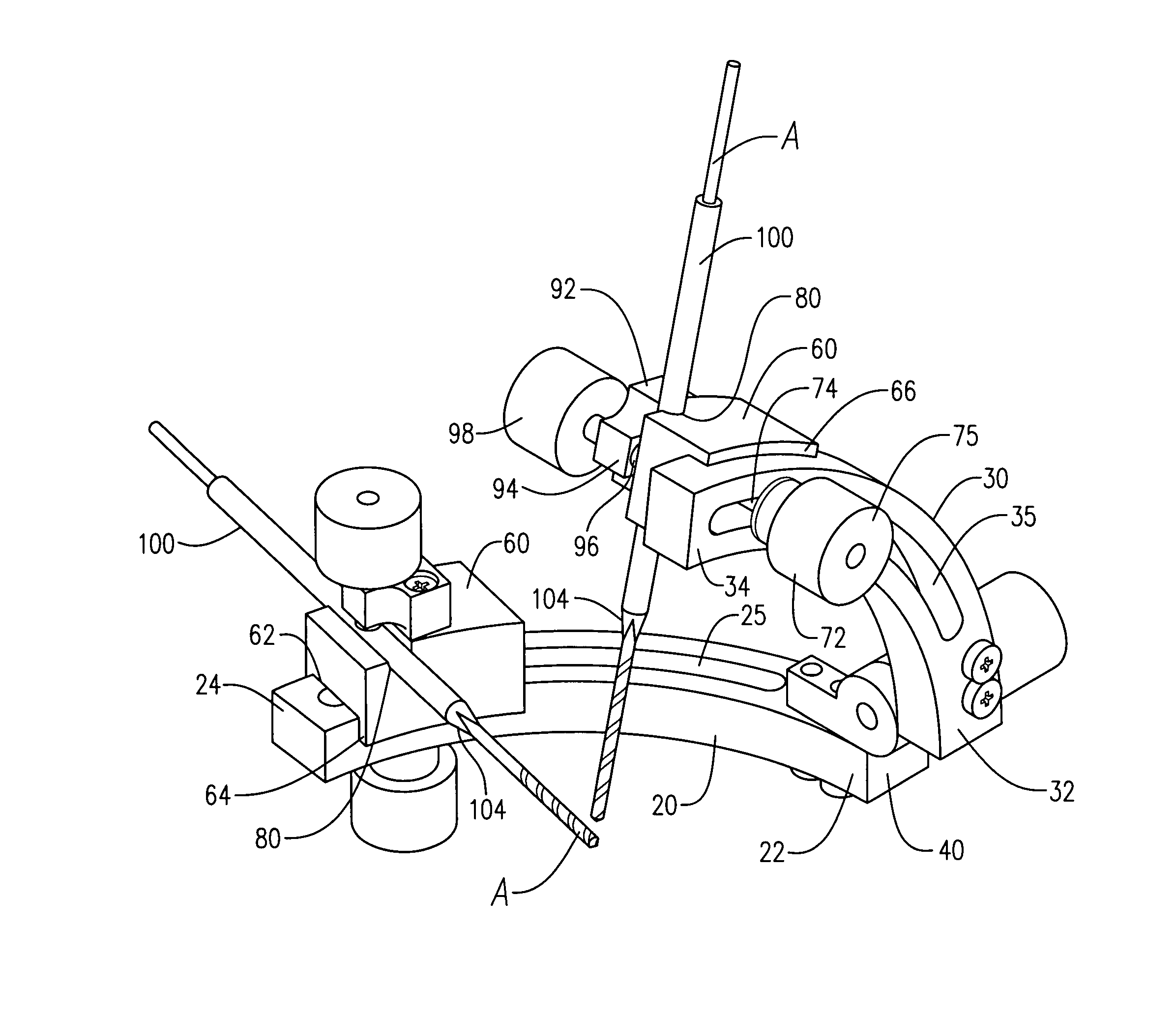
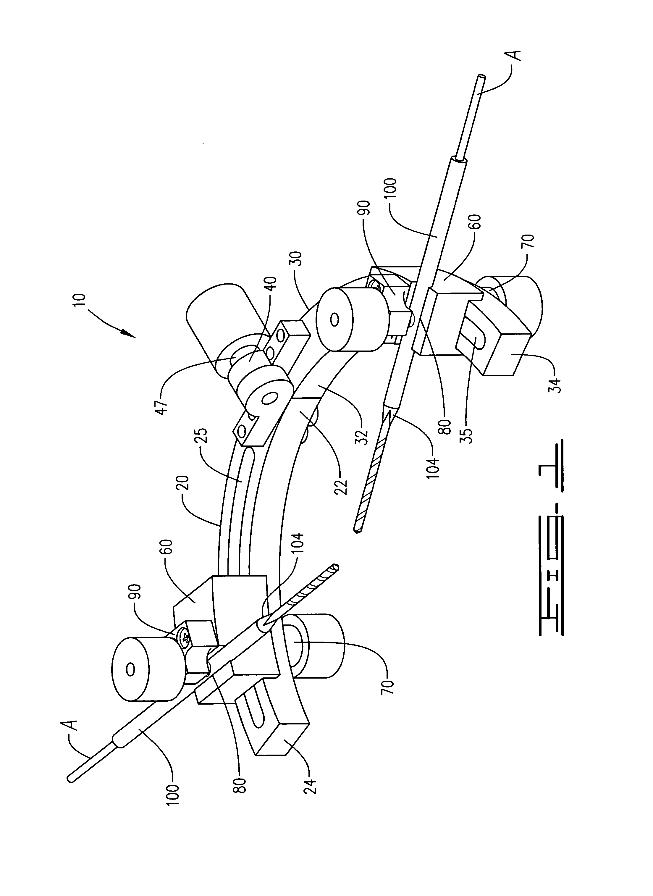
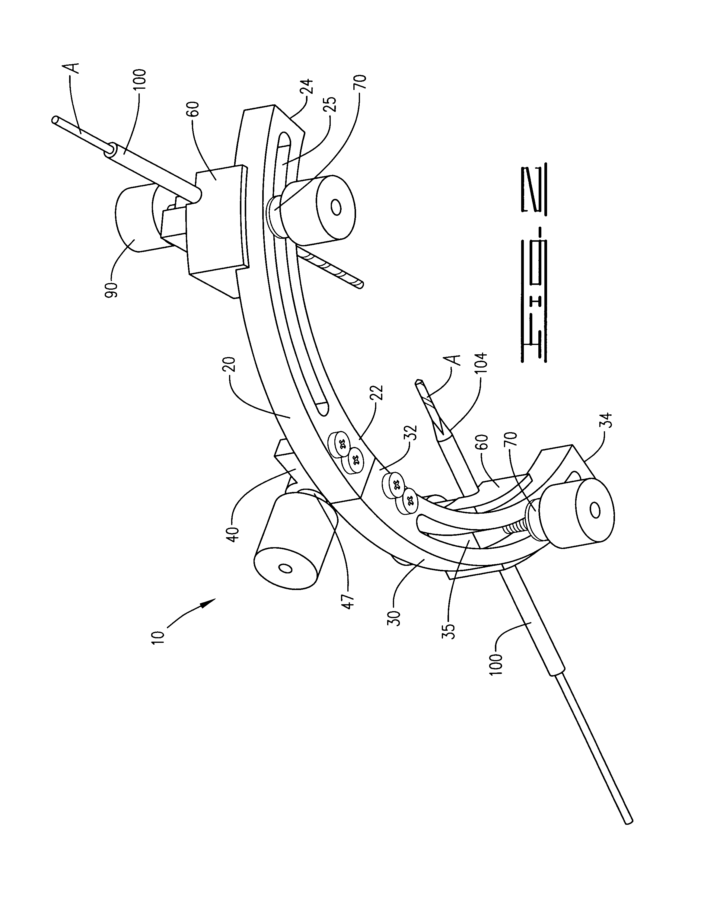
[0019]A three dimensional axis dual drill guide 10, as disclosed in FIGS. 1-7B of the drawings is used to align and bore two intersecting bone tunnels C within a bone B through two independent bone drill guides 100 contemporaneously set and positioned at locations upon a target bone to drill a transosseous channel D within the target bone for the further passage of a suture during a joint, cartilage, bone or associated soft tissue repair operation, the drill guide 10 further comprising a first guide plate 20 defining a flat circular arc, a joint end 22, a terminal end 24 and a central arced slide groove 25, a second guide plate 30 defining a flat circular arc, a joint end 32, a terminal end 34 and a central arced slide groove 35, each respective joint end pivotally connected by a joint 40 which can be disconnected, pivoted at an angle between 20 degrees and 180 degrees, and also secured to maintain an angle between the first guide plate 20 and the second guide plate 30 by a joint se...


PUM


Abstract

A multi-positional dual drill guide for use in orthopedic surgical procedures provides two independent drill guides which are independently, pivotally and removably secured along a pivotal drill guide plate comprising two separate and independent guide plate sections, selectively aligning each of the two drill guides for drilling an intersecting bone channel into a common bone from different locations for the passage of a suture and associated tissue during an orthopedic repair of a joint. The drill guide provide for three dimensional movement of the drill guides to provide a range of drilling angles from nearly zero degrees up to 180-degrees apart and in a three dimensional array, the drill.

Description

CROSS REFERENCE TO RELATED APPLICATIONS[0001]NoneBACKGROUND OF THE INVENTION[0002]1. Field of Invention[0003]A multi-positional dual drill guide for use in orthopedic surgical procedures during an orthopedic repair of a joint, cartilage, bone or associated soft tissues, provides two independent drill guide to properly align a pair of holes being drilled into a common bone from different locations to intersect and form a common channel for the passage of a suture and associated tissue during an orthopedic repair of a joint wherein the suture or other repair material is passed through the bone tunnels with specially designed tools that work in conjunction with the drill guide.[0004]2. Description of Prior Art[0005]A preliminary review of prior art patents was conducted by the applicant which reveal prior art patents in a similar field or having similar use. However, the prior art inventions do not disclose the same or similar elements as the present full range multi-positional bone dr...

Claims


Application Information

Patent Timeline
IPC IPC(8): A61B17/17
CPCA61B17/1714A61B17/1796
Inventor JORDAN, CHRISTOPHER
Owner JORDAN CHRISTOPHER
Why Eureka
Try Eureka