Surgical abrader with suction port proximal to bearing

a proximal bearing and surgical technology, applied in the field of surgery, can solve the problems of abrading operation, instrument vulnerable to binding between the inner and outer tubes,

Active Publication Date: 2006-07-18
ARTHREX
View PDF5 Cites 264 Cited by
  • Summary
  • Abstract
  • Description
  • Claims
  • Application Information

AI Technical Summary

Benefits of technology

[0008]The present invention overcomes the disadvantages of the prior art and fulfills the needs noted above by providing a surgical abrading instrument having an aspiration section that features a suction port disposed in an outer bearing tube of the instrument and proximal to a distal bearing which, in turn, is disposed proximal to an abrading head. Preferably, the suction po

Problems solved by technology

Further, tight tolerances between the inner and outer tubes necessary to provide an effective tissue-cutting actio

Method used


Image

  • Surgical abrader with suction port proximal to bearing
  • Surgical abrader with suction port proximal to bearing
  • Surgical abrader with suction port proximal to bearing

Examples


Embodiment Construction

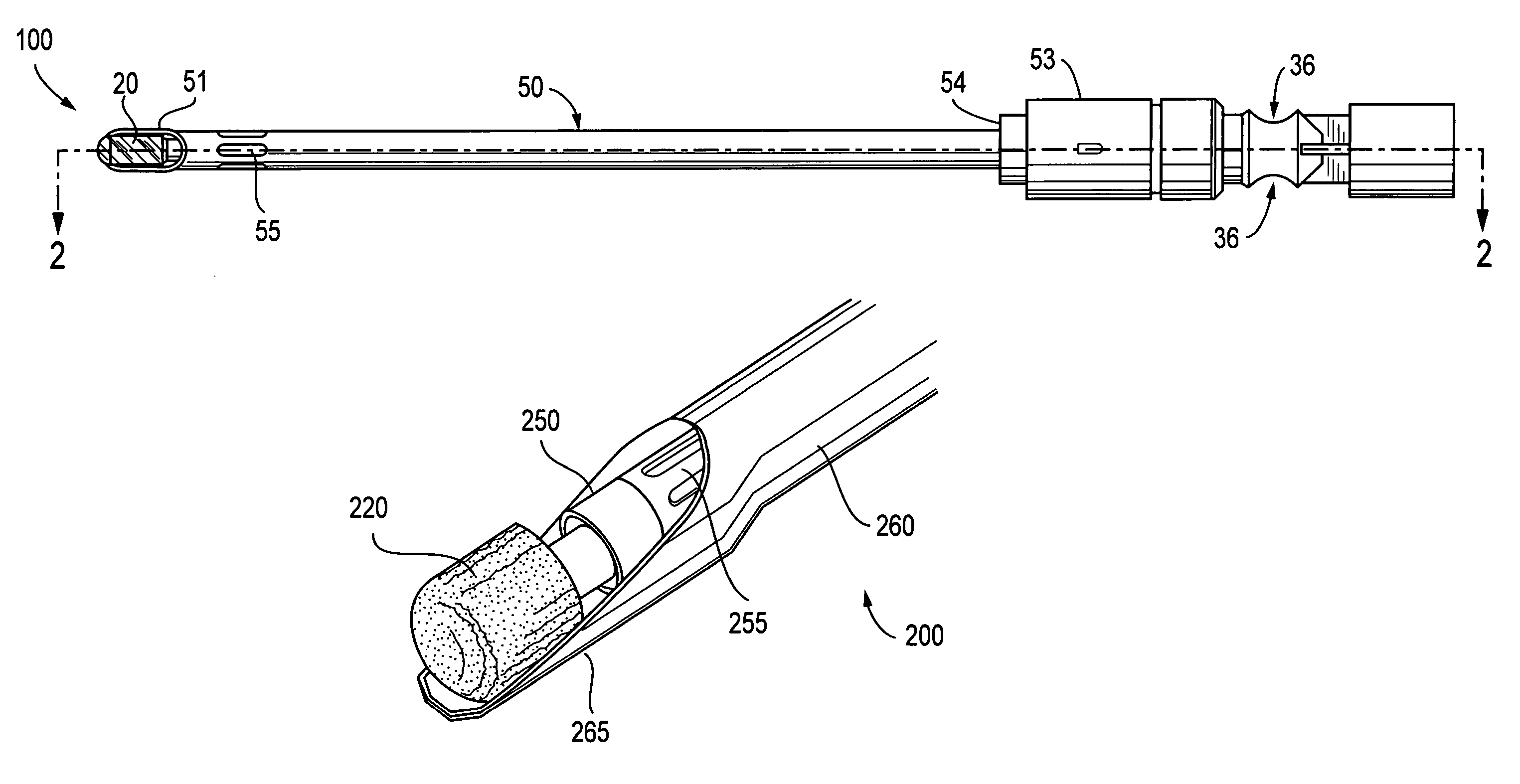
[0019]The present invention provides a surgical abrading instrument configured to reduce blockage of the instrument and eliminate the need for manually clearing the abrader. The surgical abrading instrument of the present invention includes a suction region disposed in an outer bearing tube of the instrument and proximal to a distal bearing, which, in turn, is disposed proximal to an abrading head. The suction region is in communication with an opening leading to the lumen of an inner tube. Debris produced during the abrading procedure is drawn by aspiration from the operative site through the suction region of the bearing tube and into the hollow inner tube.

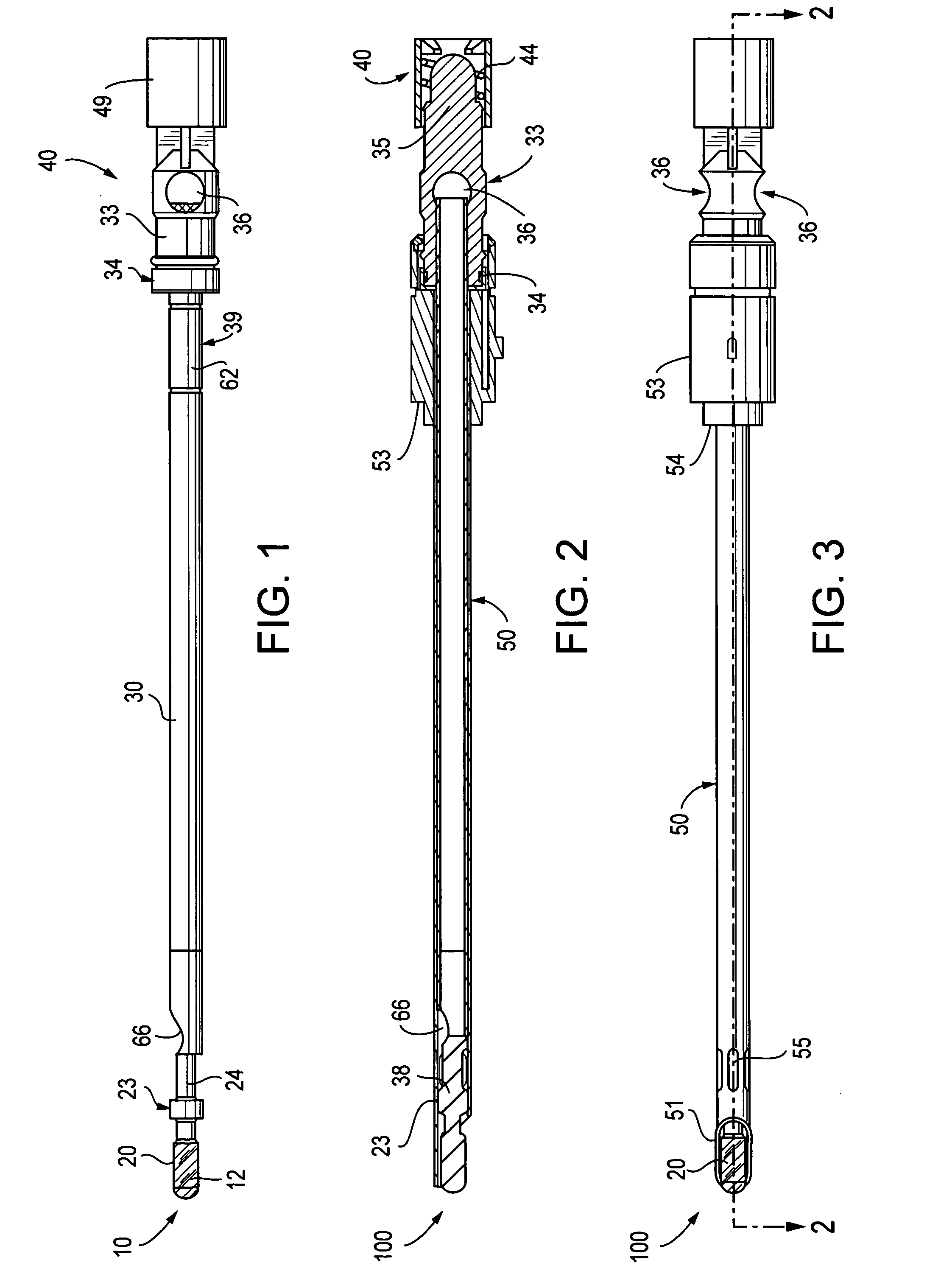
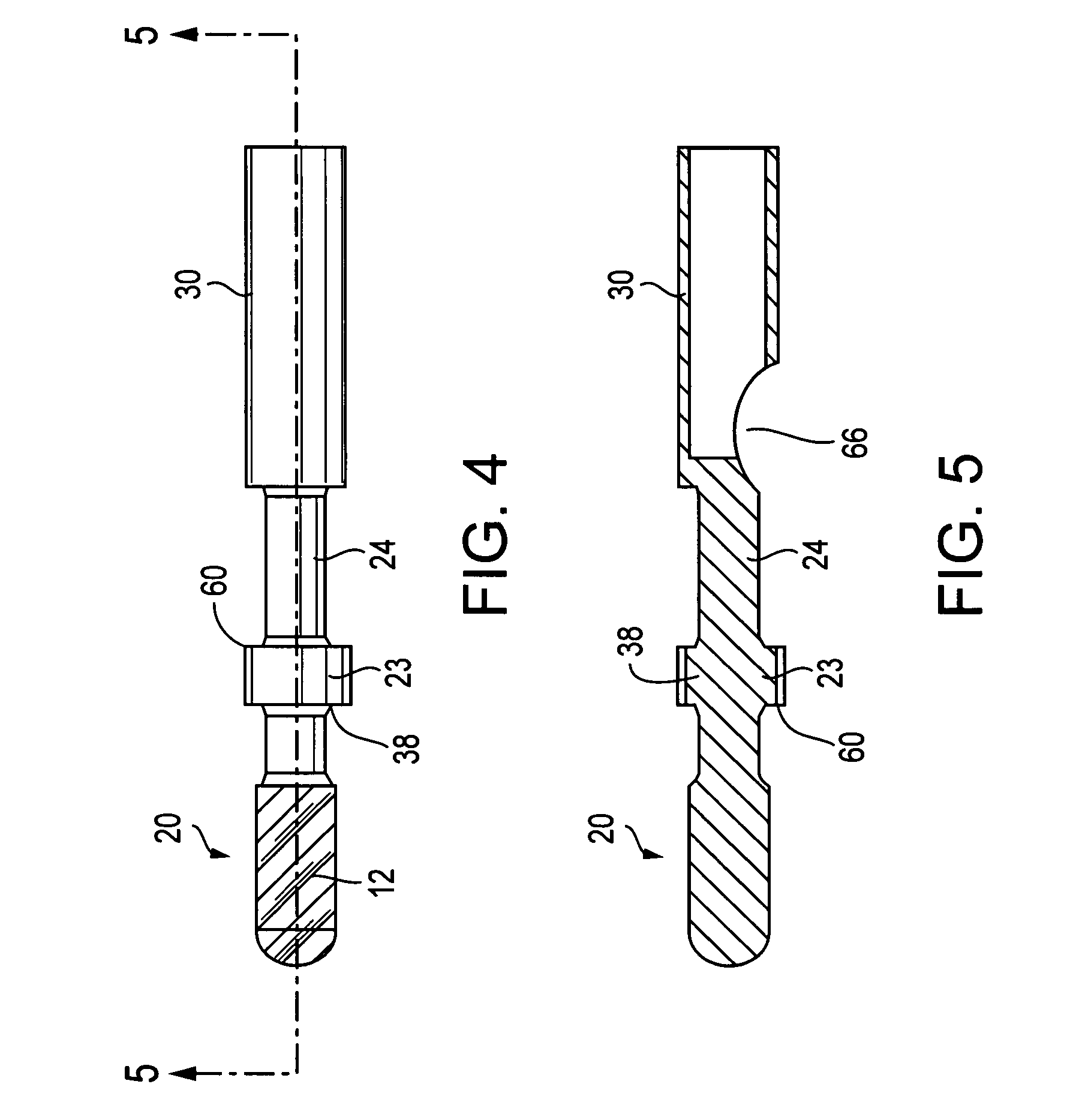
[0020]Referring now to the drawings, where like elements are designated by like reference numerals, FIG. 1 illustrates an inner tube assembly 10 of a surgical abrading instrument 100 (FIGS. 2–3) according to the present invention. Inner tube assembly 10 is adapted to rotate within a fixed bearing tube 50 (FIGS. 2–3). The inner t...


PUM


Abstract

An apparatus for abrading tissue includes a bearing tube having distal and proximal ends, and a suction port formed distally in a sidewall of the bearing tube. An inner tube disposed within the bearing tube has a distal opening, the distal opening being located proximal of the suction port in the sidewall of the bearing tube. A solid transition region extending distally from the inner tube is disposed distal to the distal opening. An abrading element supported distally by the solid transition region is used to perform orthopedic abrading procedures. The outer diameter of the abrading element is greater than the inner diameter of the bearing tube. Debris generated by abrading procedures is aspirated through the suction port formed in the sidewall of the bearing tube and into the lumen of the inner tube. A hooded sheath extends distally from the bearing tube, or optionally from a sheath tube provided over the bearing tube.

Description

[0001]This application claims the benefit of U.S. Provisional Application No. 60 / 453,196, filed Mar. 11, 2003.FIELD OF THE INVENTION[0002]The present invention relates to the field of surgery and, more particularly, to methods and instruments for abrading tissue during arthroscopic procedures.BACKGROUND OF THE INVENTION[0003]Methods and surgical instruments for abrading tissue are known in the art. Typically, surgical abrading instruments are sized and shaped to be inserted into the body through a small opening in the flesh, as would be used in arthroscopic surgical procedures. U.S. Pat. No. 4,842,578 to Johnson et al. discloses a surgical abrading instrument that includes the combination of a distally, side-supported inner drive tube carrying on its end an abrading element, and a fixed bearing tube surrounding the inner tube and providing at a bearing region the distal support for the inner tube. A distal extension of the bearing tube provides a sheath for a portion of the abrading...

Claims


Application Information

Patent Timeline
IPC IPC(8): A61B17/00A61B17/32A61M1/00
CPCA61B17/32002A61B2217/005A61B2017/320004
Inventor HACKER, RANDALL L.SCHMIEDING, JOHN W.
Owner ARTHREX
Why Eureka
Try Eureka