Controlled architecture ceramic composites by stereolithography

a technology of ceramic composites and controlled ceramics, applied in the direction of ceramicware, programme control, instruments, etc., can solve the problems of affecting the porosity of the interconnected porous system of osteo-conduction, the ideal pore dimension and the and the inability to determine or achieve ideal pore dimensions and porosity of the interconnected porous system for osteo-conduction

Inactive Publication Date: 2001-09-04
UNITED STATES SURGICAL CORP +2
View PDF7 Cites 285 Cited by
  • Summary
  • Abstract
  • Description
  • Claims
  • Application Information

AI Technical Summary

Benefits of technology

It is a further object of this invention to provide such ceramic composites with a macroshape, a network microarchitecture, a porosity and pore sizes in the network which can be simultaneously and precisely controlled or may be designed during the production process.
It is yet another object of this invention to provide a fabrication technique that enables the osteon-evacuated micro and macroarchitecture of the bone to be duplicated.
Preferably and more specifically, the process uses a stereolithographic technique for laser patterning and photocuring a ceramic / polymer material. See Hull, U.S. Pat. No. 4,575,330, "Apparatus for production of three-dimensional objects by stereolithography," (1986) for details of the technique. The technique relies upon laser photocuring a dense colloidal dispersion into a desired complex three-dimensional shape. The shape may be obtained from a CT scan file of a bone and is rendered into a CAD file that is readable by the stereolithography instrument. The software is commercially available for translating the CT scan data to SL machine readable files. Additionally, the patient's defect site can be scanned to exactly match the implant or the device. See Crook, "Method for representing a patient's treatment site as data for use with a CAD CAM device," U.S. Pat. No. 5,452,407 (1995). Or the desired complex three-dimensional shape can be produced by conventional CAD (computer aided design) processes. The process can form a high quality orthopedic device that can also dimensionally match the bone structure of a patient. Stereolitho-graphy applied to bone implants has two potential advantages. The first is the rapid fabrication of individually shaped implants; and the second is fabrication of micro-porous materials that allow penetration of the cells into the graft and promotes new bone formation over time.

Problems solved by technology

The fabrication of such osteon-evacuated complex architecture or controlled microarchitecture and controlled porosity ceramic and ceramic / polymer composite structures is difficult and has been the subject of many investigations.
The ideal pore dimensions and the porosity of the interconnected porous system for osteo-conduction has still not been determined or achieved.
However, porositys attained by natural corals, though reproducing that of tissues, appear questionable owing to the nature of the walls which contain impurities which are able to disturb the reaction mechanisms between ceramics and hard tissues.
None of the current fabrication techniques enable the osteon-evacuated micro-architecture of the bone to be duplicated and none of these techniques allow the fabrication of a predetermined, tailored macro and micro-architecture.
The main disadvantages of these replicas are there is no control of the architecture and the structures have inferior mechanical properties which limits their load bearing clinical applications.
However, the pore size was limited to only several microns.

Method used


Image

  • Controlled architecture ceramic composites by stereolithography
  • Controlled architecture ceramic composites by stereolithography

Examples


Embodiment Construction

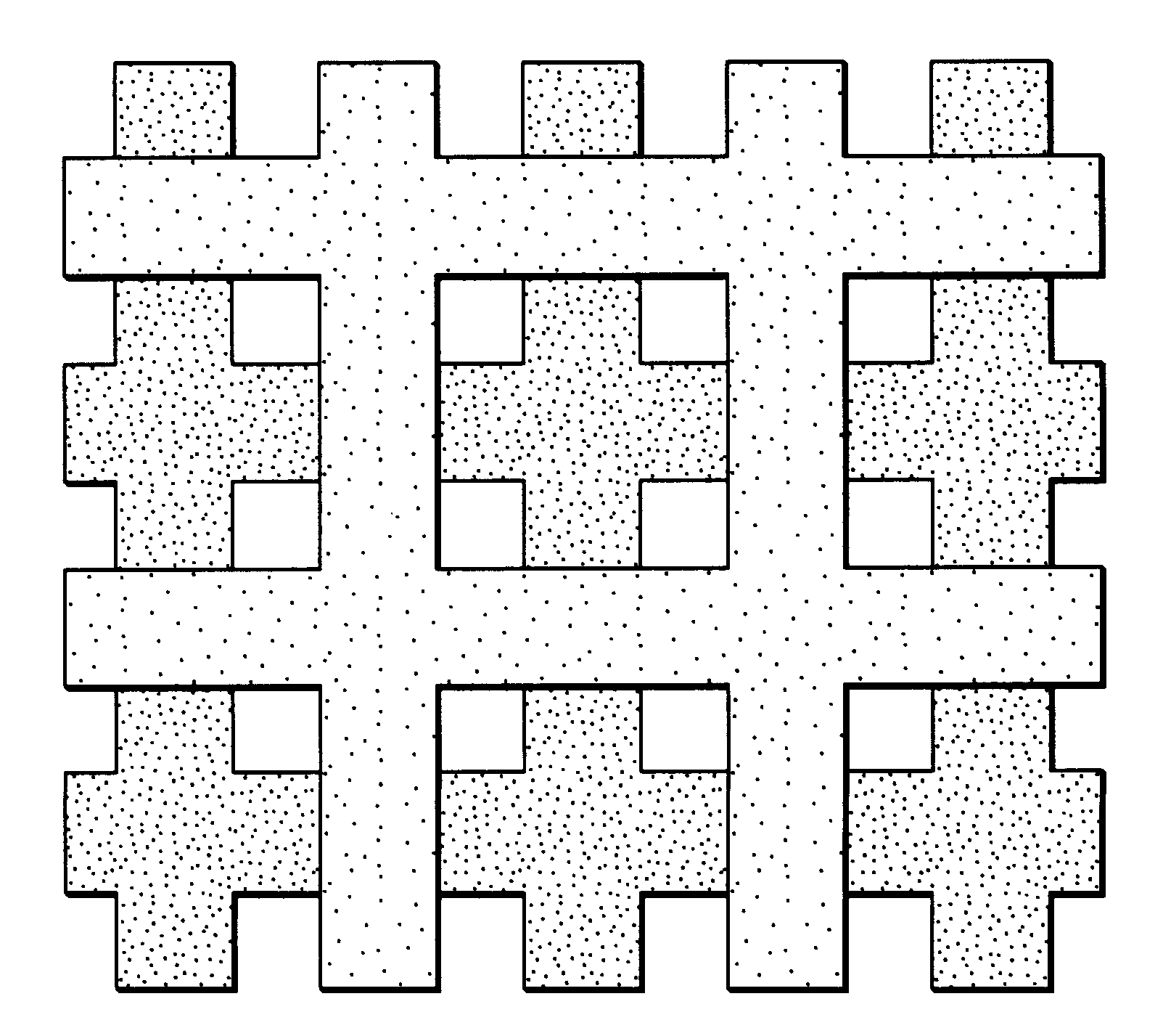
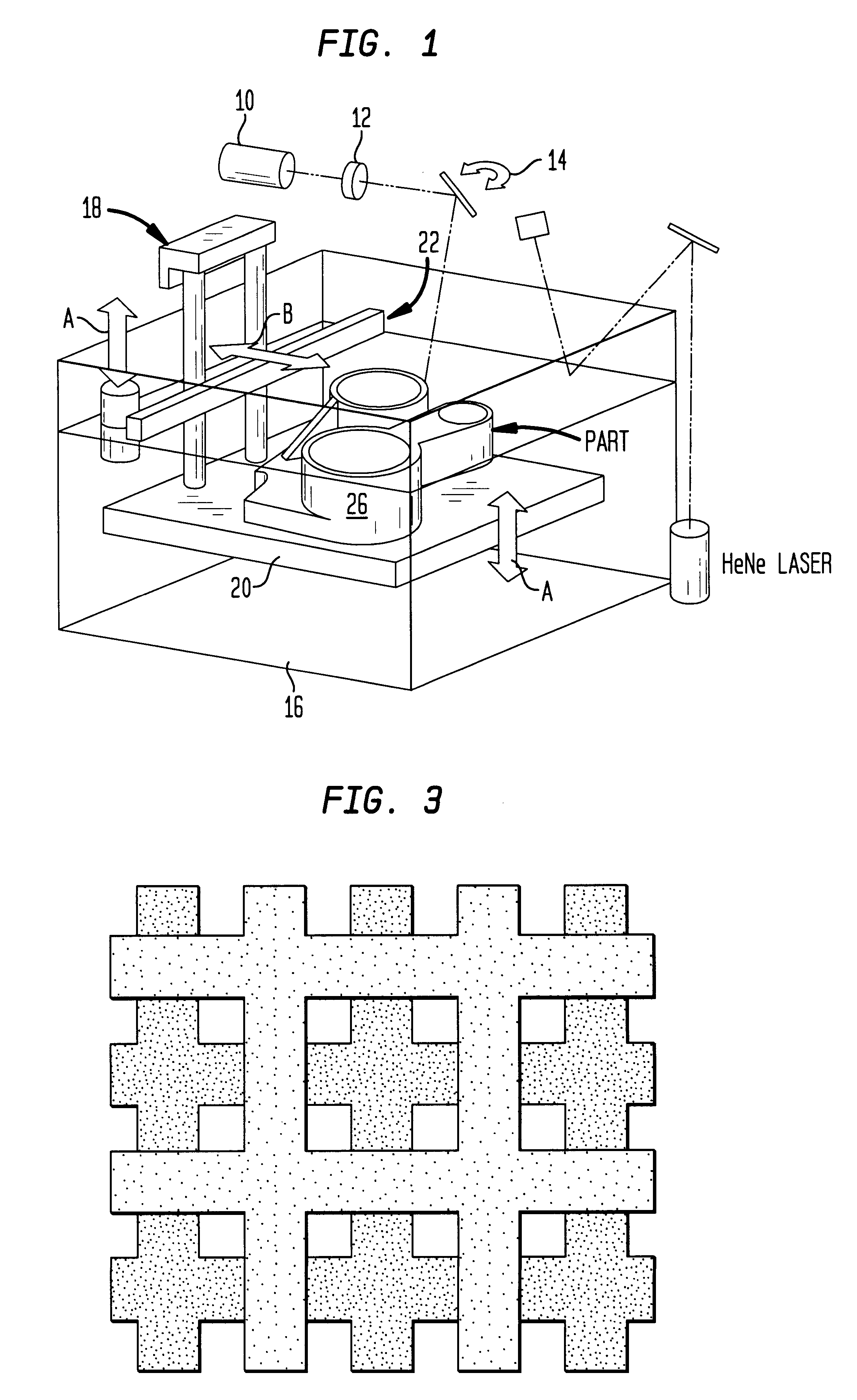
An MRI scan of the bone image was taken from NIH Visible Human Project (Http: / / www.nlm.nih.gov / research / visible / visible_human.html) and was converted into a three dimensional CAD image using "Materialize" computer software and then sliced into thin slices using "Maestro" (3D Systems, Inc.). Computer assisted tomography (CAT) and magnetic resonance imaging (MRI) scanning systems provide high resolution images of the internal structure of the human body. The Visible Human project from NIH provides a database of the MRI and CT scan of the entire human body. During the past few years, these scanning techniques, along with the associated software and hardware have undergone substantial development. It is now possible to represent the images into 3-D surface models or solid models. "Materialize" software converts the MRI or CT images into 3-D models.

Parts were then fabricated on 3D Systems SLA 250 / 40 stereolithography machine from a high concentration (48 volume%) aqueous alumina dispersi...


PUM

PropertyMeasurementUnit
porosityaaaaaaaaaa
pore sizeaaaaaaaaaa
volume fraction porosityaaaaaaaaaa

Abstract

A process for producing a ceramic composite having a porous network. The process includes providing a photocurable ceramic dispersion. The dispersion consists of a photocurable polymer and a ceramic composition. The surface of the dispersion is scanned with a laser to cure the photocurable polymer to produce a photocured polymer / ceramic composition. The photocured composition useful as a polymer / ceramic composite, or the polymer phase can be removed by heating to a first temperature that is sufficient to burn out the photocured polymer. It is then heated to a second temperature that is higher than the first temperature and is sufficient to sinter the ceramic composition to produce a purely ceramic composition having a porous network.Preferably and more specifically, the process uses a stereolithographic technique for laser scanning. The process can form a high quality orthopedic implant that dimensionally matches the bone structure of a patient. The technique relies upon laser photocuring a dense colloidal dispersion into a desired complex three-dimensional shape. The shape is obtained from a CAT scan file of a bone and is rendered into a CAD file that is readable by the stereolithography instrument. Or the shape is obtained directly from a CAD file that is readable by the stereolithography instrument.

Description

1. Field of the InventionThis invention relates to ceramic and polymer / ceramic composites having a porous network wherein the macro-shape of the composite, microarchitecture of the network, porosity and the pore sizes in the network can be simultaneously and precisely controlled or designed. This invention further relates to methods for producing such composites by stereolithography and the varied uses thereof.2. Related ArtMicro-architecture and pore size are extremely important for osteoconduction in ceramic bone grafts. All of our organs (such as liver, bone, and kidney) constitute a "Parenchyma," which is the physiologically active component, and the "Stroma," which is the framework that supports the organization of the parenchyma. In soft tissue, loss of parenchyma with maintenance of stroma allows a remarkable degree of regeneration and repair. Thus to design an implant for osteoconduction it is desirable to mimic the architecture of the interstitial or stromal bone. An ideali...

Claims


Application Information

Patent Timeline
Patent Type & Authority Patents(United States)
IPC IPC(8): A61F2/28A61F2/30A61L27/02A61L27/44A61L27/00B29C67/00C04B38/06G03F7/00A61F2/02A61F2/00
CPCA61F2/28A61L27/02A61L27/446B29C67/0066C04B38/067G03F7/0037A61F2/30942C04B35/00C04B38/0054C04B41/0036Y10S623/901A61F2/30965A61F2002/2825A61F2002/2835A61F2002/30011A61F2002/30062A61F2002/30915A61F2002/30948A61F2002/30952A61F2002/30962A61F2002/30968A61F2002/3097A61F2002/30971A61F2210/0004A61F2250/0023A61F2310/00203A61F2310/00215A61F2310/00239A61F2310/00293A61F2310/00317B29K2709/02C04B2111/00836G05B2219/49008G05B2219/49013B33Y10/00B33Y80/00B29C64/135
Inventor GARG, RAJEEVPRUD'HOMME, ROBERT K.AKSAY, ILHAN A.JANAS, VICTOR F.TENHUISEN, KEVOR S.HUXEL, SHAWN T.
Owner UNITED STATES SURGICAL CORP
Why Eureka
Try Eureka