
Facial Bone Surgery Apparatus For Medical

Inactive Publication Date: 2009-04-23
MEDIKAN
View PDF6 Cites 16 Cited by
  • Summary
  • Abstract
  • Description
  • Claims
  • Application Information

AI Technical Summary

Benefits of technology

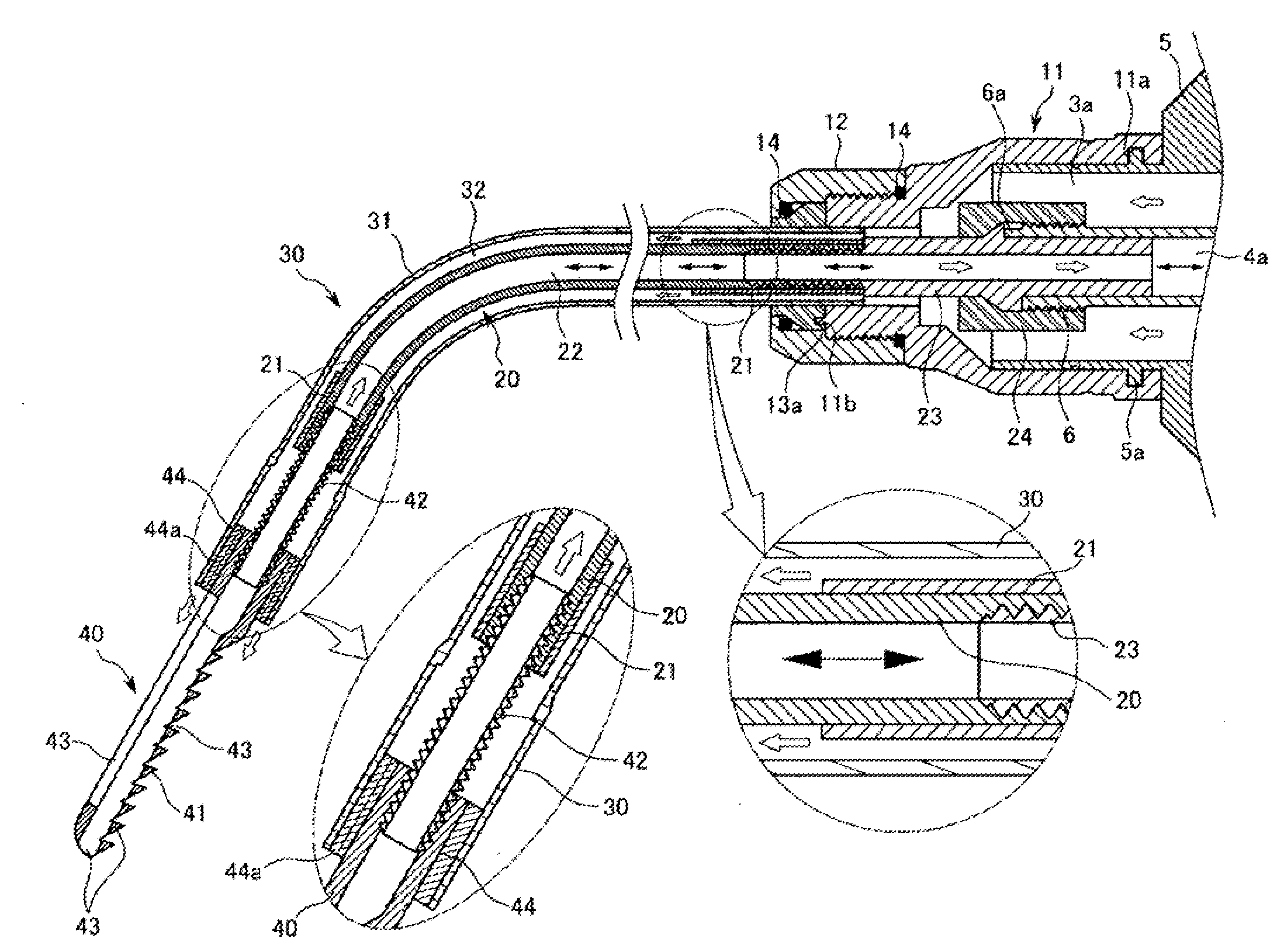
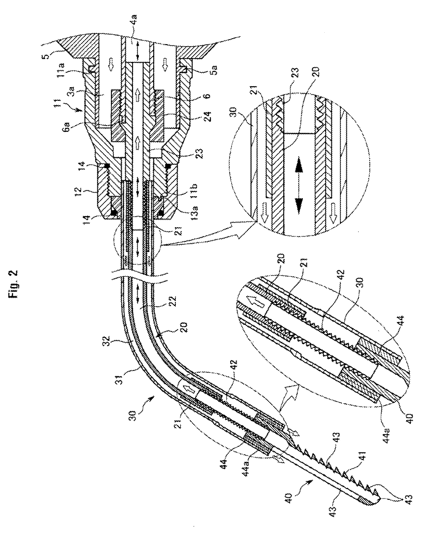
[0009]In order to solve the problems, it is an object of the present invention to provide a facial bone surgery apparatus for medical treatment having a bent section formed at an insertion part to be inserted into an incision part to enable power transmission through the bent section, such that a cutting operation can be performed in a different direction than a reciprocating direction of a straight reciprocating member installed at a hand piece, thereby enabling surgical operations under the condition of a limited incision or approach angle.
[0020]According to a facial bone surgery apparatus for medical treatment of the present invention, it is possible to perform bone cutting in a direction different from an introduction direction of a cutting tool because a bent section is formed at an outer pipe to enable power transmission in a direction different from a moving direction of a straight reciprocating member of a hand piece. In addition, it is possible to perform various surgical operations under the condition of a limited incision or approach angle because an assembly angle of the cutting tool and an assembly angle of the outer pipe can be implemented in various embodiments.

Problems solved by technology

Since the oscillating sagittal saw method is designed such that a saw blade moves with a certain angle, extension or reduction in length of the saw blade may cause variation of operation sections and cutting power, thereby making it difficult to cut a portion spaced apart from an incision part.
Therefore, in the case that various approach angles and various cutting angles are required during the approach and entry of portions of the apparatus through the limited incision or if a surgeon is faced with a limited approach angle, such as during facial bone surgery, it was difficult to perform the surgical operation.

Method used


Image

  • Facial Bone Surgery Apparatus For Medical
  • Facial Bone Surgery Apparatus For Medical
  • Facial Bone Surgery Apparatus For Medical

Examples


Embodiment Construction

[0031]Exemplary embodiments of the present invention will now be described in detail with reference to the accompanying drawings.

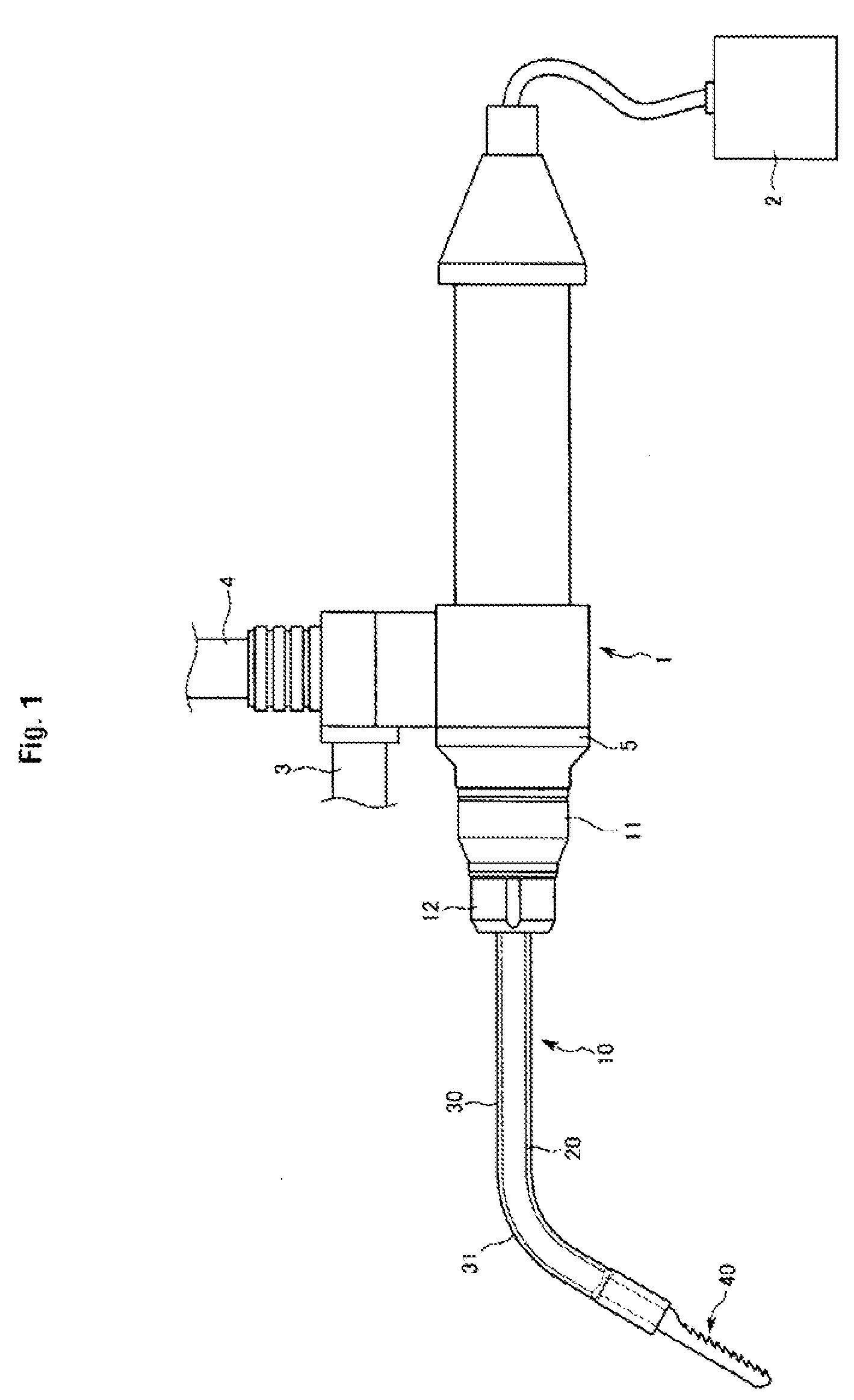
[0032]FIG. 1 is a front view of a facial bone surgery apparatus adapted to a hand piece in accordance with the present invention. As shown, the facial bone surgery apparatus 10 in accordance with the present invention is detachably assembled to a hand piece 1 by a connection means including a connection tube 11 and a fixing nut 12.

[0033]The hand piece 1 is an example of Korean Patent Registration No. 589118 issued to the inventor. While not shown in FIG. 1, the hand piece 1 includes a straight reciprocating means driven by power of an external drive means 2, a saline solution supply means connected to a saline solution supply connection pipe 3 to supply a saline solution into the surgery apparatus, and a foreign substance suction means connected to a suction unit connection pipe to suck foreign substances generated during surgical operations.

[0034]The faci...


PUM

PropertyMeasurementUnit
Angleaaaaaaaaaa
Flexibilityaaaaaaaaaa

Abstract

The present invention relates to a facial bone surgery apparatus for medical treatment assembled to a hand piece having a straight reciprocating part, a saline solution supply part and a foreign substance discharge part, which includes: an inner pipe reciprocally movable together the straight reciprocating means and having a hollow shape of a soft flexible material; an outer pipe connected to a main body of the hand piece and installed at an outer periphery of the inner pipe to guide reciprocal movement of the inner pipe, and having a bent section formed between both ends thereof, the outer pipe being formed of a hard material; and a cutting tool assembled at an end of the inner pipe to reciprocate therewith and reciprocally guided by the outer pipe.

Description

CROSS-REFERENCE TO PRIORITY APPLICATIONS[0001]This application is a continuation of and claims priority to the commonly assigned Korean Application 10-2006-0064612 (filed Jul. 10, 2006, in the Korean Patent Office) and the commonly assigned International Patent Application No. PCT / KR2007 / 003341 (filed Jul. 10, 2007, in the Korean Patent Office), both of which are hereby incorporated by reference in their entirety.FIELD OF THE INVENTION[0002]The present invention relates to a facial bone surgery apparatus for medical treatment, and more particularly, to a facial bone surgery apparatus for medical treatment coupled to a medical hand piece including a straight reciprocating means, a saline solution supply means and a foreign substance discharge means, and used for contour correction such as a reduction of a lower jawbone or cheekbone and removal of a bone tumor or bone spur.BACKGROUND[0003]A surgery apparatus for performing bone amputation or bone cutting can generally be classified in...

Claims


Application Information

Patent Timeline
IPC IPC(8): A61B17/14A61B17/00A61B17/32
CPCA61B17/14A61B2217/005A61B17/148B23D49/11B23D51/16A61B2217/007A61B17/144A61B17/1644A61B17/1659A61B17/1673A61B17/56A61B2017/00792
Inventor LEE, HEEYOUNGLEE, JUNSEOK
Owner MEDIKAN
Learn More