Pedicle screw assembly having a retractable screw tip for facilitating the securement of the pedicle screw assembly to a spinal vertebra

a technology of pedicle screw and screw assembly, which is applied in the field of pedicle screw assembly having a retractable screw tip, can solve the problems of significant radiation exposure and a series of relatively complex steps for the securement of such a device to the vertebra, and achieve the effect of facilitating the securement of the pedicle screw assembly

Inactive Publication Date: 2010-11-04
UNIVERSITY OF TOLEDO
View PDF16 Cites 19 Cited by
  • Summary
  • Abstract
  • Description
  • Claims
  • Application Information

AI Technical Summary

Benefits of technology

[0008]This invention relates to a pedicle screw assembly having a retractable screw tip that facilitates the securement of the pedicle screw assembly to a spinal vertebra in a minimally invasive fashion during an orthopedic surgical procedure. The pedicle screw assembly includes a body portion including a head and a shank. The shank includes an outer surface with a thread provided thereon, an end having a cutting tip provided thereon, and a bore extending inwardly from the end and having an internally threaded region provided therein. The pedicle screw assembly also includes a tip portion including a body having a cutting edge and a shank extending from the body. The shank has an externally threaded region provided thereon that cooperates with the internally threaded region of the bore to permit movement of the tip portion relative to the body portion between extended and retracted positions.

Problems solved by technology

The securement of such a device to the vertebra usually involves a series of relatively complex steps.
Although this procedure for securing a conventional pedicle screw to a vertebra has functioned satisfactorily, it can be seen that the fluoroscopic or other imaging or navigational techniques are frequently employed, which is time consuming and can result in significant radiation exposure.

Method used


Image

  • Pedicle screw assembly having a retractable screw tip for facilitating the securement of the pedicle screw assembly to a spinal vertebra
  • Pedicle screw assembly having a retractable screw tip for facilitating the securement of the pedicle screw assembly to a spinal vertebra
  • Pedicle screw assembly having a retractable screw tip for facilitating the securement of the pedicle screw assembly to a spinal vertebra

Examples


first embodiment

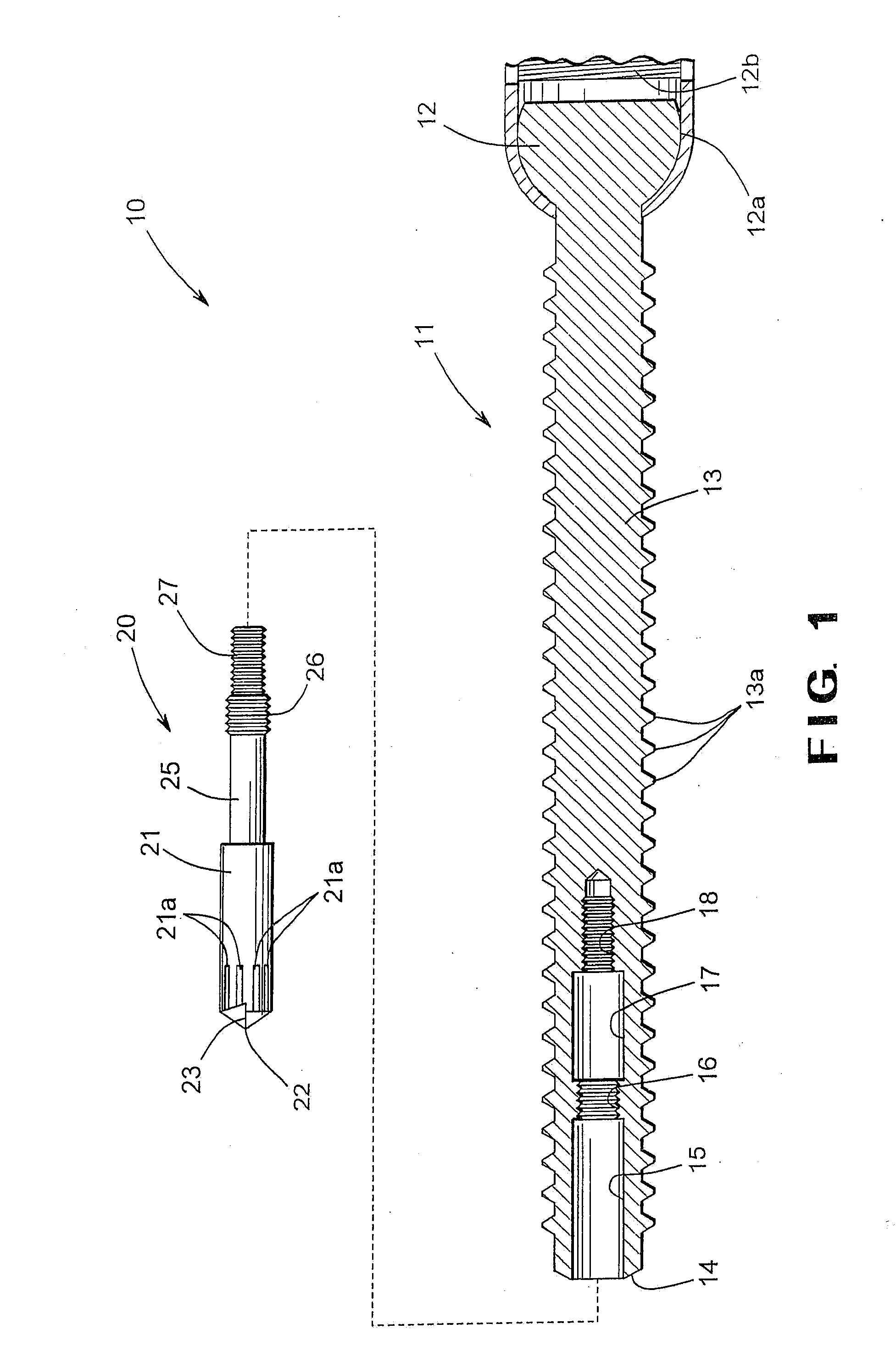
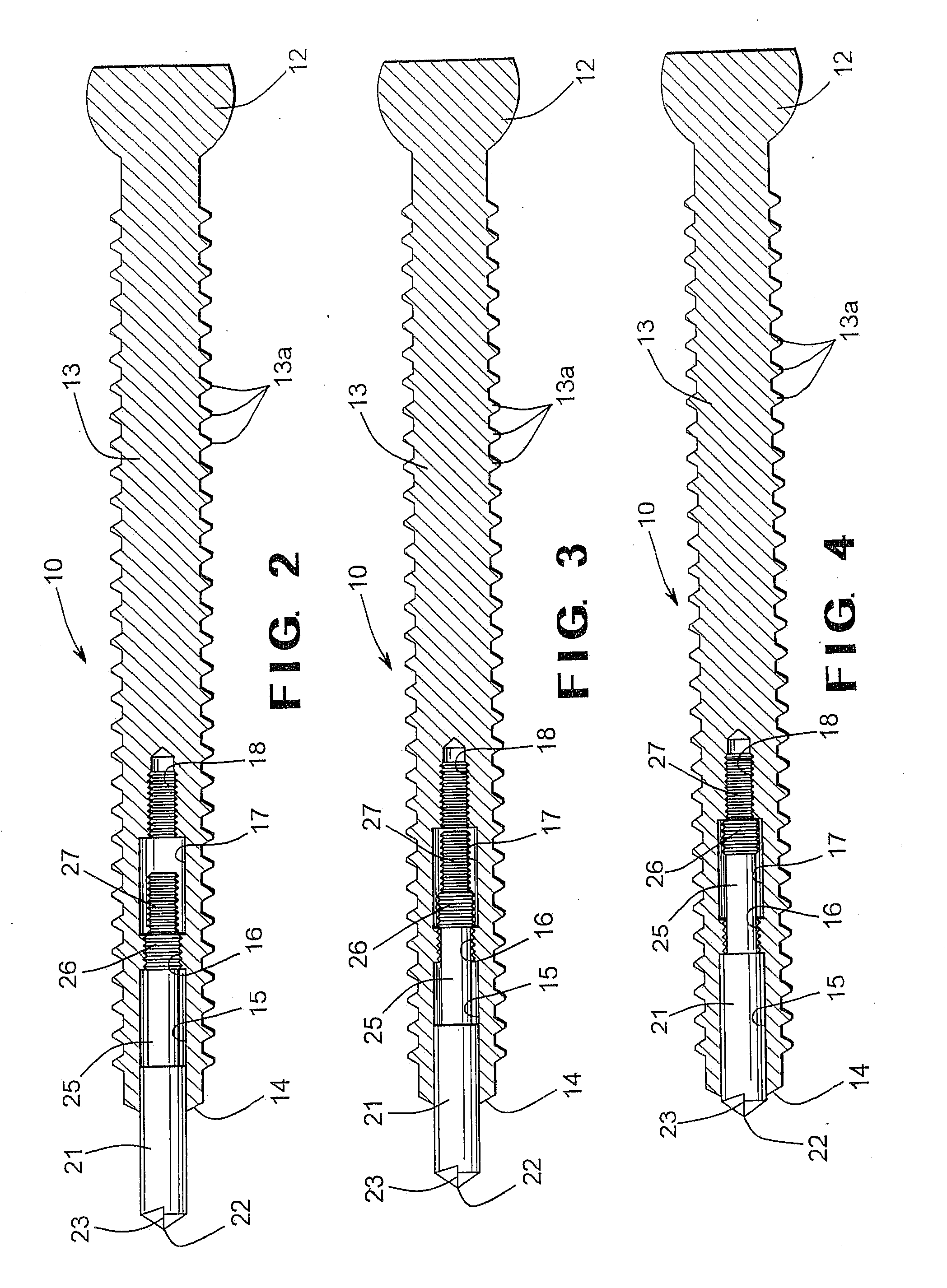
[0030]Referring now to the drawings, there is illustrated in FIGS. 1 through 4 a pedicle screw assembly, indicated generally at 10, in accordance with this invention. As will be explained in detail below, the illustrated pedicle screw assembly 10 can be used to facilitate the securement of a device to a bone. However, the pedicle screw assembly 10 of this invention may be used for any desired purpose or in any desired surgical procedure.

[0031]The first embodiment of the pedicle screw assembly 10 includes a body portion, indicated generally at 11, having a head 12 provided at a first end thereof and an elongated shank 13 that extends from the head portion 12. The body portion 11 of the pedicle screw assembly 10 may be formed from any desired material, such as titanium, stainless steel, cobalt-chrome, or other medically-approved biomaterial. In the illustrated embodiment, the head 12 of the body portion 11 is generally semi-spherical in shape. However, the head 12 may be formed having...

third embodiment

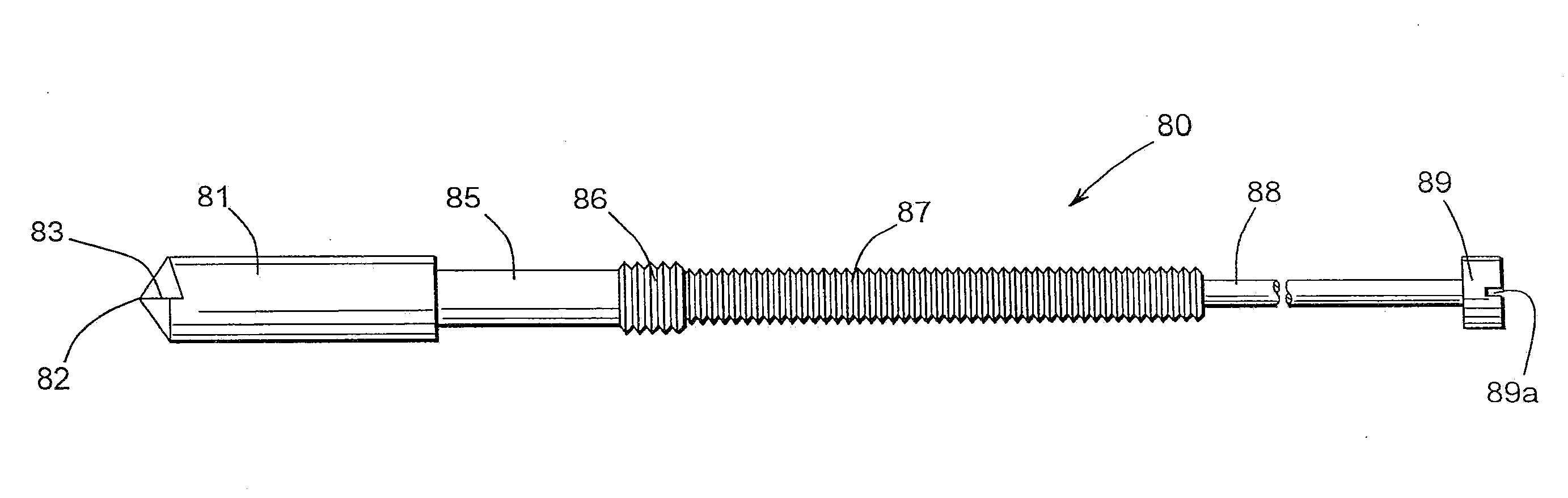
[0057]The tip portion 60 additionally includes an elongated extension 68 that terminates in an end 69. The end 69 has a drive mechanism provided therein that is adapted to cooperate with a conventional rotation tool (see FIG. 19) to effect rotation of the tip portion 60 relative to the body portion 51. In the illustrated embodiment, the drive mechanism is a slot 69a that can cooperate with a conventional flat-head screwdriver. However, the drive mechanism can be embodied as any conventional structure for accomplishing this purpose. The elongated extension 68 and the end 69 can be formed integrally with the remainder of the tip portion 61 or can be formed separately and secured thereto, as described above. Otherwise, the pedicle screw assembly 50 functions in a manner similar to the embodiments of the pedicle screw assembly 10 and 30 described above.

[0058]FIGS. 12 and 13 illustrate a fourth embodiment of a pedicle screw assembly, indicated generally at 70, in accordance with this inv...


PUM


Abstract

A pedicle screw assembly has a retractable screw tip that facilitates the securement of the pedicle screw assembly to a spinal vertebra in a minimally invasive fashion during an orthopedic surgical procedure. The pedicle screw assembly includes a body portion including a head and a shank. The shank includes an outer surface with a thread provided thereon, an end having a cutting tip provided thereon, and a bore extending inwardly from the end and having an internally threaded region provided therein. The pedicle screw assembly also includes a tip portion including a body having a cutting edge and a shank extending from the body. The shank has an externally threaded region provided thereon that cooperates with the internally threaded region of the bore to permit movement of the tip portion relative to the body portion between extended and retracted positions.

Description

CROSS-REFERENCE TO RELATED APPLICATIONS[0001]This application is a continuation-in-part patent application of U.S. patent application Ser. No. 12 / 535,026, filed Aug. 4, 2009, which claimed the benefit of U.S. Provisional Application No. 61 / 086,447, filed Aug. 5, 2008. The disclosures of both of those applications are incorporated herein by reference.STATEMENT REGARDING FEDERALLY SPONSORED RESEARCH OR DEVELOPMENT[0002]Not applicable.BACKGROUND OF THE INVENTION[0003]This invention relates in general to fasteners that are used to secure devices to bones in surgical procedures. In particular, this invention relates to a pedicle screw assembly having a retractable screw tip that facilitates the securement of the pedicle screw assembly to a spinal vertebra in a minimally invasive fashion during an orthopedic surgical procedure.[0004]Many surgical procedures involve the securement of a device to a bone. For example, during an orthopedic surgical procedure, it is often necessary to secure a...

Claims


Application Information

Patent Timeline
Patent Type & Authority Applications(United States)
IPC IPC(8): A61B17/86A61B17/56
CPCA61B17/8685A61B17/864
Inventor BIYANI, ASHOKDURIVAGE, GARY
Owner UNIVERSITY OF TOLEDO
Why Eureka
Try Eureka