Hair pin

a technology of hairpins and clips, applied in the field of hairpins, can solve the problems of not having a composite function of strong hairpins with a further difficulty in holding a lot of hairs, and the clipping portion does not hold the hairs effectively, so as to improve the utility of the clipping portion, improve the marketability, and effectively press

Inactive Publication Date: 2015-12-17
KIM CHAN SOO +1
View PDF16 Cites 6 Cited by
  • Summary
  • Abstract
  • Description
  • Claims
  • Application Information

AI Technical Summary

Benefits of technology

[0015]With the above configuration, the hairpin according to the present invention presses and holds the hair in place by the upper and lower clips, in which the upper clip is provided with the convex holding portion for holding a lot of hairs in place, and the resiliently pressing portion for pressing and holding the hairs, thereby strongly holding a lot of hairs in place to improve its marketability relative to the related art.
[0016]In particular, by the wavy structure of the resiliently pressing portion, the structure of proving various resilient force by connecting both ends of the resiliently pressing portion or forming one end thereof as the free end, and the guide structure of the resiliently pressing portion, the hairs are more effectively pressed and held by the resiliently pressing portion, thereby remarkably improving the utility thereof.
[0017]Further, when the upper and lower clips are made of resin through molding, since the structure of the convex portion and the resiliently pressing portion of the upper clip are simple, the configuration of the mold for the upper clip can be simple, and also, the molding work using the mold can be also easily performed, thereby remarkably reducing the manufacture cost thereof. In particular, alignment of the resiliently pressing portion with the slot can obviate any requirement for sliding side cores during molding.

Problems solved by technology

The above-described hairpins of the related art have a problem in that since clipping portions of the upper and lower clips are formed in a flat shape, the clipping portions do not only hold the hairs effectively, but also do not retain a lot of hairs.
However, the hairpins of the related art do not have a composite function of strongly holding a lot of hairs.
In particular, in the case where the hairpins are made of resin, the hairpins have a further difficulty in holding a lot of hairs in place.

Method used


Image

  • Hair pin
  • Hair pin
  • Hair pin

Examples


Embodiment Construction

[0039]A hairpin according to an embodiment of the present invention will be hereafter described in detail with reference to the accompanying drawings.

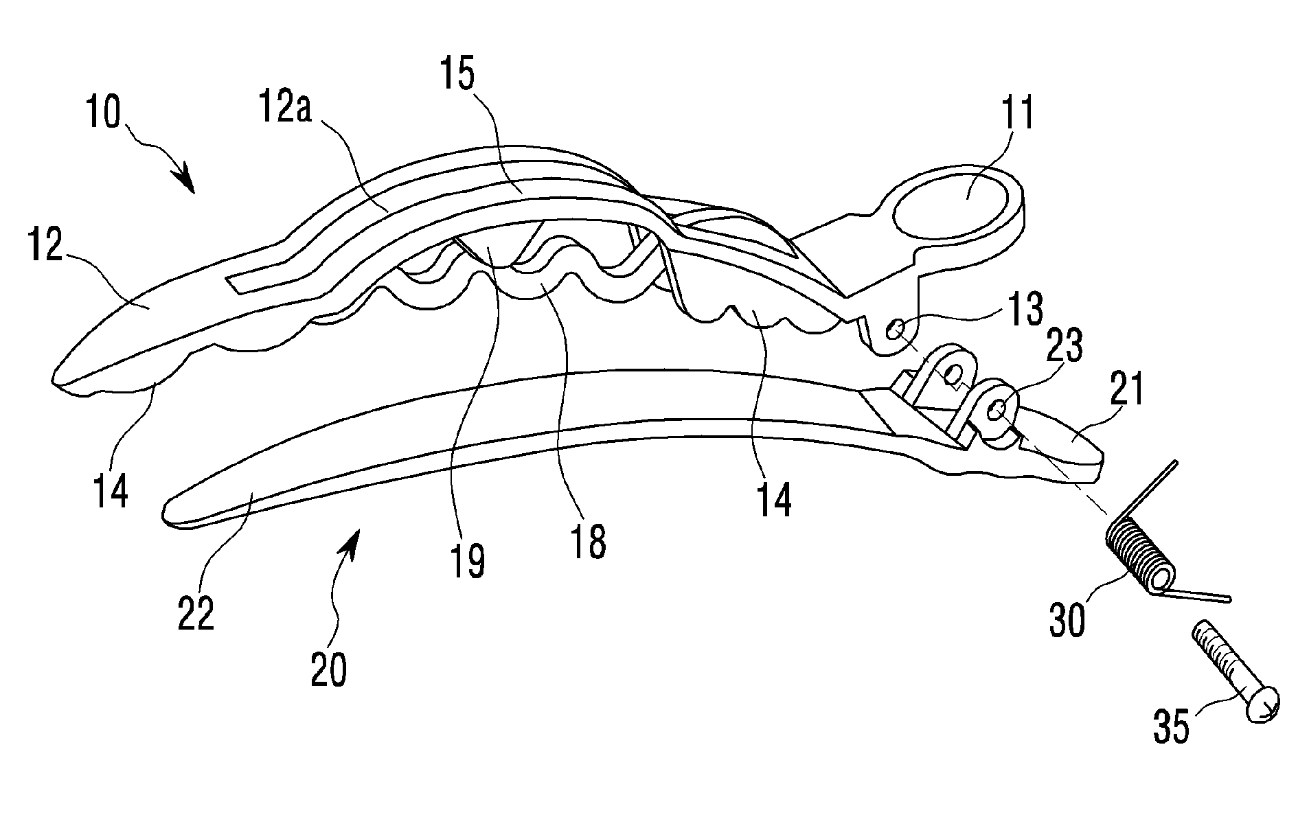
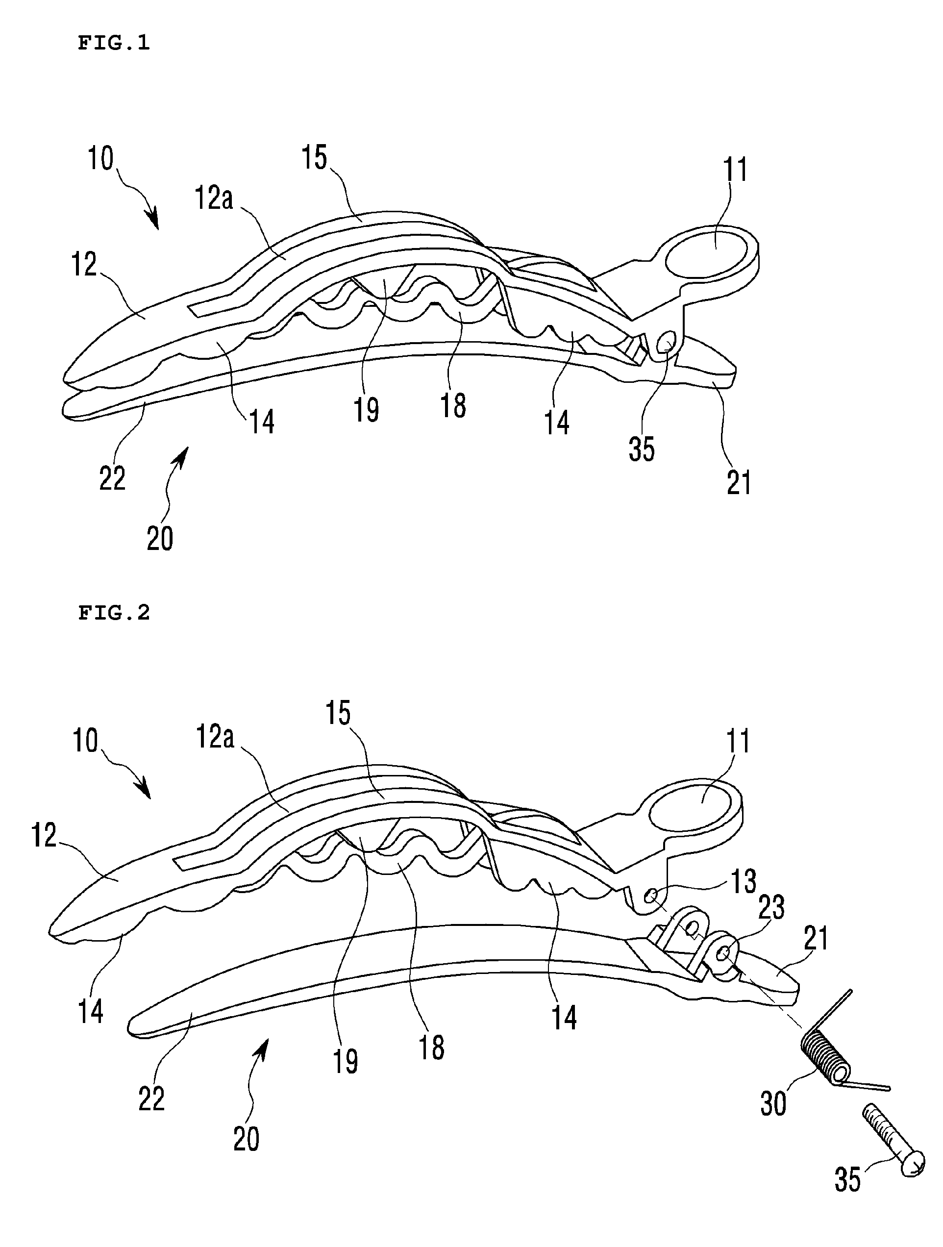
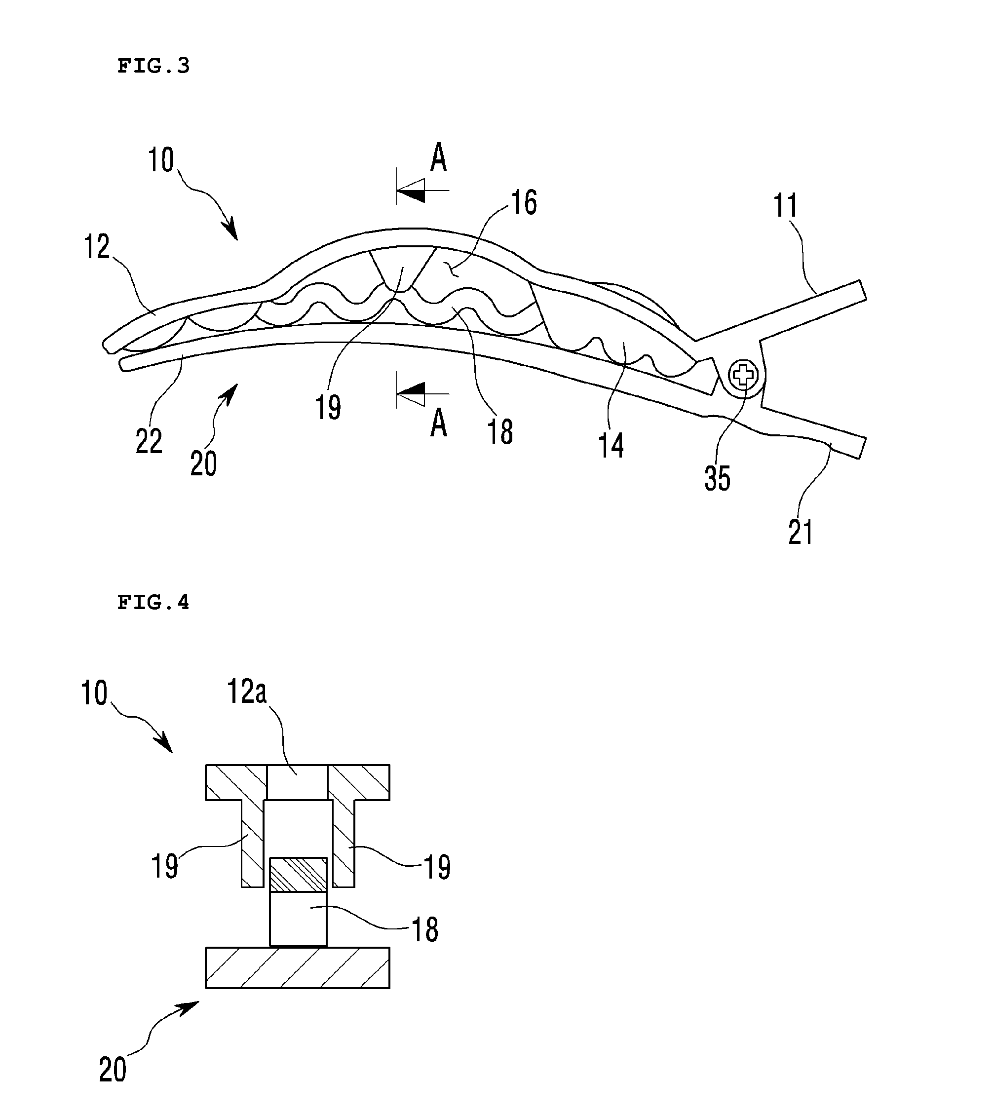
[0040]The hairpin of the present invention includes, as illustrated in FIGS. 1 to 5, upper and lower clips 10 and 20 having finger pressing portions 11 and 21 and clipping portions 12 and 22, a hinge shaft 35 that is inserted in holes 13 and 23 formed in the upper and lower clips 10 and 20, and a torsion spring 30 through which the hinge shaft 35 passes, in order to hold hairs in place by tension force of the clipping portions 12 and 22 of the upper and lower clips.

[0041]In particular, the clipping portion 12 of the upper clip 10 has a convex holding portion 15 protruding outwardly from an inner center of the clipping portion to form a space 16 for retaining the hairs therein, and a resiliently pressing portion 18 integrally extending from the clipping portion below the convex holding portion 15 in a longitudinal direction of the clipp...


PUM


Abstract

A hairpin to press and hold hairs in place which includes upper and lower clips (10 and 20) each having finger pressing portions (11 and 21) and clipping portions (12 and 22); a hinge shaft (35) inserted in holes (13 and 23) formed in the upper and lower clips (10 and 2); a torsion spring (30) through which the hinge shaft (35) passes, in which hairs are pressed and held in place by tension force of the clipping portions (12 and 22) of the upper and lower clips. The clipping portion (12) of the upper clip (10) has a convex holding portion (15) protruding outwardly from an inner center of the clipping portion to form a space (16) for retaining hairs. A resiliently pressing portion (18) integrally extends from the clipping portion below the convex holding portion (15) to press and hold the hairs in place.

Description

FIELD OF THE INVENTION[0001]The present invention relates to a hairpin (otherwise known as a hair-grip) for use in beauty shops or the like to press and hold hairs in place, and more specifically, to a hairpin including upper and lower clips for pressing and holding hairs therebetween, in which the upper clip is provided with a convex holding portion for holding a lot of hairs in place, and a resiliently pressing portion for pressing and holding the hairs, thereby strongly holding a lot of hairs in place to improve utility thereof.BACKGROUND OF THE RELATED ART[0002]In general, hairpins, hairclips or hair-grips (hereinafter referred to a hairpin, hairclip or hair-grip) are used to hold hairs of women in a desired place or style.[0003]Various kinds of hairpins are disclosed in the art, and the hairpins generally include upper and lower clips that are connected to each other by a torsion spring and a hinge shaft to press and hold the hairs in place by tension force of the upper and low...

Claims


Application Information

Patent Timeline
Patent Type & Authority Applications(United States)
IPC IPC(8): A45D8/20
CPCA45D8/20
Inventor KIM, CHAN-SOOKIM, BUM-JIN
Owner KIM CHAN SOO
Why Eureka
Try Eureka