Downwardly extending wing tip device

a technology of wing tip and wing tip, which is applied in the direction of airflow influencers, wing adjustment, aircraft stabilisation, etc., can solve the problem of limited length of downwardly extending (anhedral) wing tip devices, and achieve the effect of increasing the ground clearance of the wing tip devices

Active Publication Date: 2015-12-17
AIRBUS OPERATIONS LTD
View PDF36 Cites 6 Cited by
  • Summary
  • Abstract
  • Description
  • Claims
  • Application Information

AI Technical Summary

Benefits of technology

[0034]for ground-based operations, configuring the wing tip device in a ground-operating configuration, in which ground-oper...

Problems solved by technology

It can be desirable to have relatively long wing tip devices, but the length of downwardly extending (anhedral) wing tip devices tends to be limited by airport operatin...

Method used


Image

  • Downwardly extending wing tip device
  • Downwardly extending wing tip device
  • Downwardly extending wing tip device

Examples


first embodiment

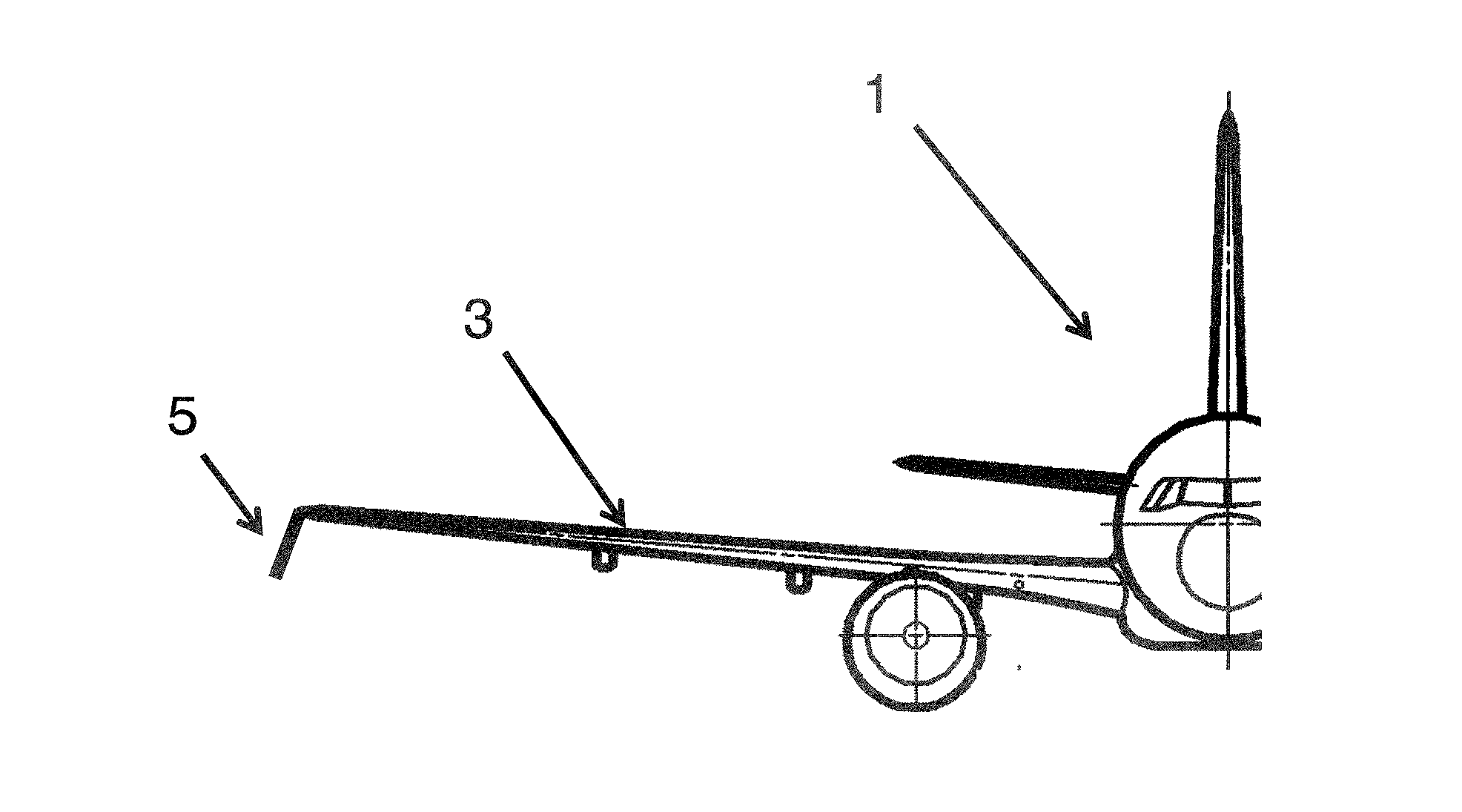
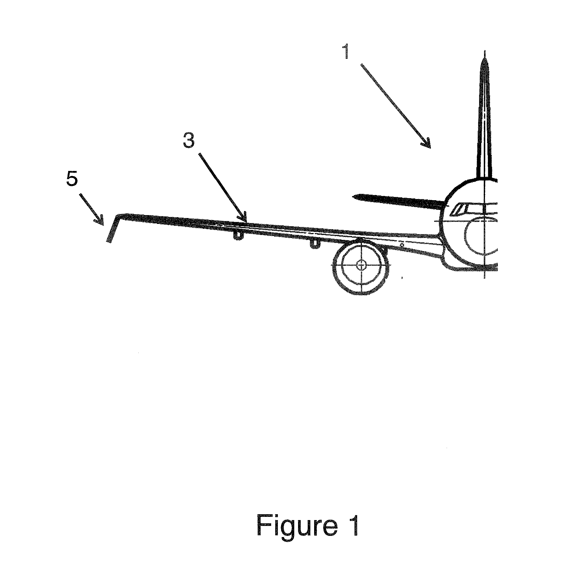
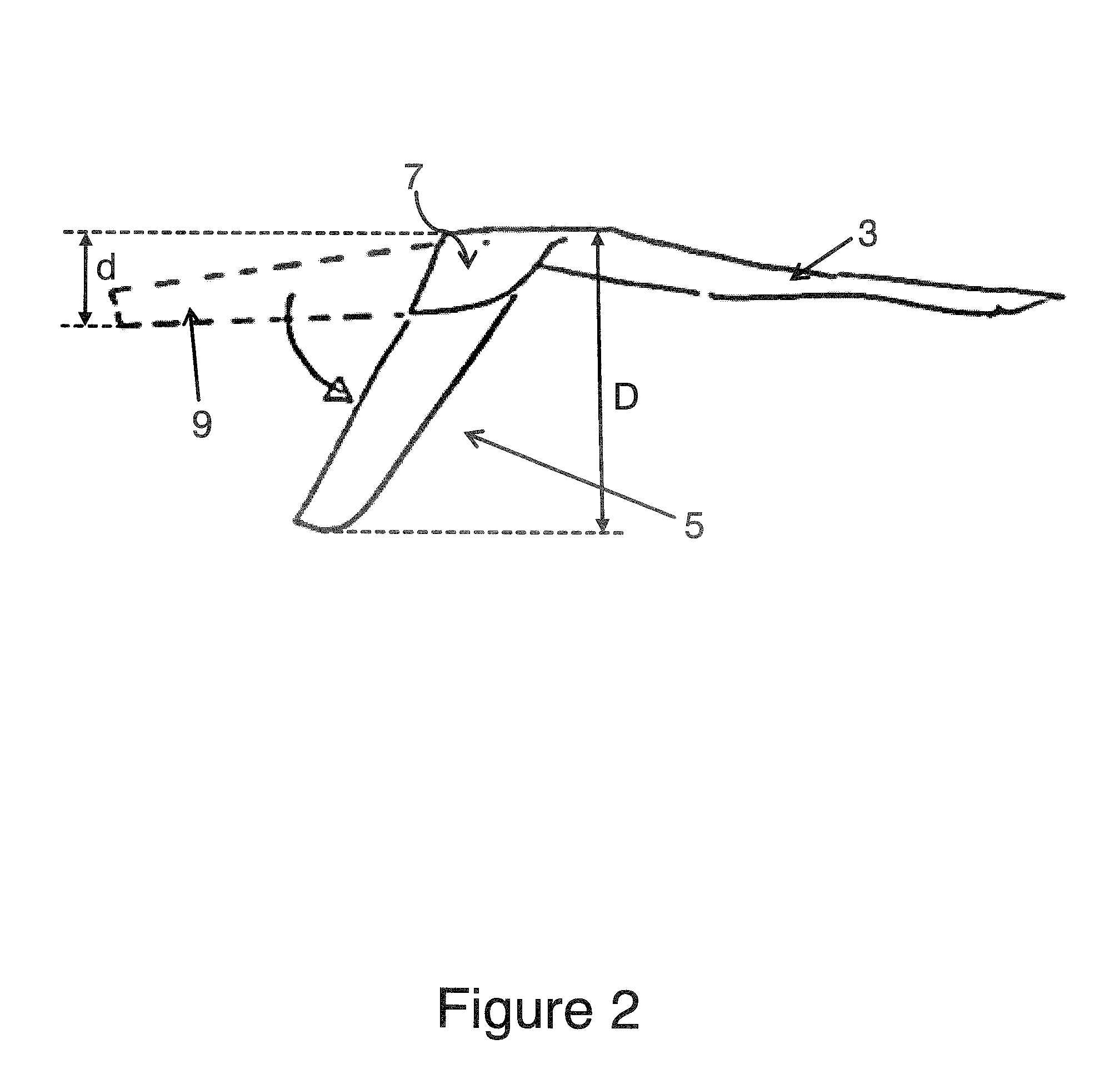
[0052]FIGS. 2, 3 and 4 show the wing tip device on the aircraft of the invention from end, plan and front elevations respectively. For the sake of clarity, the effective span increase s, created by the wing tip device, is exaggerated in the plan view of FIG. 3.

[0053]The wing tip device 5 is formed of a fixed region 7 adjoining the aircraft wing 3, and a moveable region 9. A thin extension element (not shown) on the moveable region 9 overlaps the underside of the fixed region 7. The moveable region 9 is rotatably mounted on the fixed region 7 about an axis of rotation 11 (see FIG. 4) that passes through the overlap.

[0054]In FIG. 2, the structure defining the moveable region 9 is drawn as a continuous line to show the wing tip device 5 in a high-altitude cruise configuration, and is drawn as a dashed line to show the wing tip device 5 in a ground-operating configuration (described in more detail below). In FIG. 4, the rotatable region 9 is drawn as a dashed line to show the wing tip d...

second embodiment

[0060]FIGS. 8 and 9 are front views of wing tip devices according to other embodiments of the invention. In the embodiment of FIG. 8, the upwardly extending wing tip device is fixed at a lower cant than the invention, and the bulbous body protrudes further on the lower side of the wing than the upper side. In the embodiment of FIG. 9, the bulbous region 115 is located adjacent the root of the fixed region 107 of the downwardly extending device 105, but does not extend all the way to the leading edge of the wing.

[0061]Yet another embodiment of the invention is shown in FIGS. 10 and 11. This embodiment of the invention is identical to the second embodiment except that the wing tip does not include a bulbous body at the root of the upwardly and downwardly extending devices.

[0062]In the above-mentioned embodiments, the moveable region is rotatably mounted on the underside of the structure defining the fixed region, and the axis of rotation of the moveable region '9 extends perpendicular...


PUM


Abstract

An aircraft including a wing, the end of the wing having a wing tip device, wherein the wing tip device includes a moveable region that is rotatable, about an axis of rotation extending out of the plane of the wing tip device, between: (i) a high-altitude cruise configuration in which the moveable region extends downwardly below the wing; and (ii) a ground-operating configuration in which the moveable region extends rearwardly behind the wing such that the ground clearance of the wing tip device is increased.

Description

TECHNICAL FIELD[0001]The present invention relates to an aircraft having a downwardly extending wing tip device, and to a method of configuring the wing tip device.BACKGROUND OF THE INVENTION[0002]The use of wing tip devices, such as winglets, on aircraft is well known. Such devices seek to improve the aerodynamic performance of the aircraft, typically reducing induced drag and increasing lift. It can be desirable to have relatively long wing tip devices, but the length of downwardly extending (anhedral) wing tip devices tends to be limited by airport operating rules which govern various clearances required when maneuvering around the airport (such as the span and / or ground clearance required for gate entry and safe taxiway usage). There has therefore tended to be a focus on using longer upwardly extending (dihedral) wing tip devices, than downwardly extending devices.SUMMARY OF THE INVENTION[0003]According to a first aspect of the invention, there is provided an air vehicle compris...

Claims


Application Information

Patent Timeline
IPC IPC(8): B64C3/56B64C5/08
CPCB64C5/08B64C3/56B64C23/076Y02T50/10
Inventor BRADSHAW, PHILIP JOHN TEMPLETONWHITEHOUSE, IAN ROYWOOD, NORMANALEXANDER, STUARTRANDALL, JOHN DAVID
Owner AIRBUS OPERATIONS LTD
Why Eureka
Try Eureka