
Flow deflector

a deflector and flow technology, applied in the direction of heat exchange apparatus safety devices, machines/engines, light and heating apparatus, etc., can solve the problems of structural damage, high risk of thermal fatigue failure, and difficulty in mounting a floating core in the heat exchanger

Inactive Publication Date: 2015-12-17
BORGWARNER EMISSIONS SYST SPAIN S L U
View PDF8 Cites 2 Cited by
  • Summary
  • Abstract
  • Description
  • Claims
  • Application Information

AI Technical Summary

Benefits of technology

This patent is about a new heat exchanger design that allows for more efficient cooling with a smaller amount of coolant fluid. The design includes a deflector that helps to improve cooling performance. This design helps to reduce the space between the bundle of tubes and the inner chamber of the shell, which makes it easier to cool the inner chamber. Overall, this design allows for better cooling efficiency and performance with a smaller amount of coolant fluid.

Problems solved by technology

The absence of cooling causes overheating in non-cooled areas with respect to other surrounding areas and therefore higher risk of thermal fatigue failure.
Nevertheless, these welded plates make mounting a floating core in the heat exchanger difficult, and they cannot completely restrict the space since mechanical interferences with the core would be produced in the event of the existence of vibrations, which would end up causing structural damage.

Method used


Image

  • Flow deflector
  • Flow deflector
  • Flow deflector

Examples


Embodiment Construction

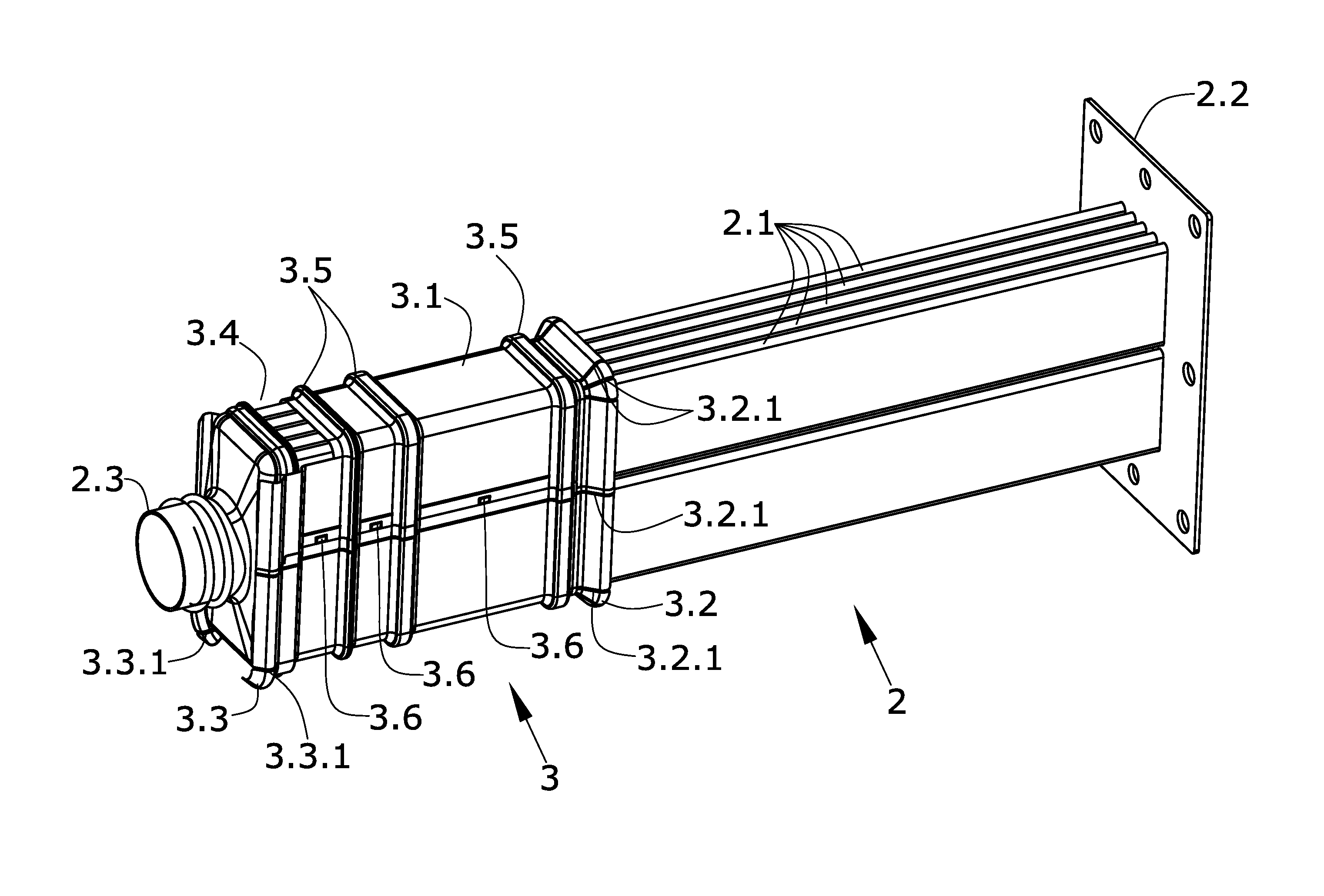
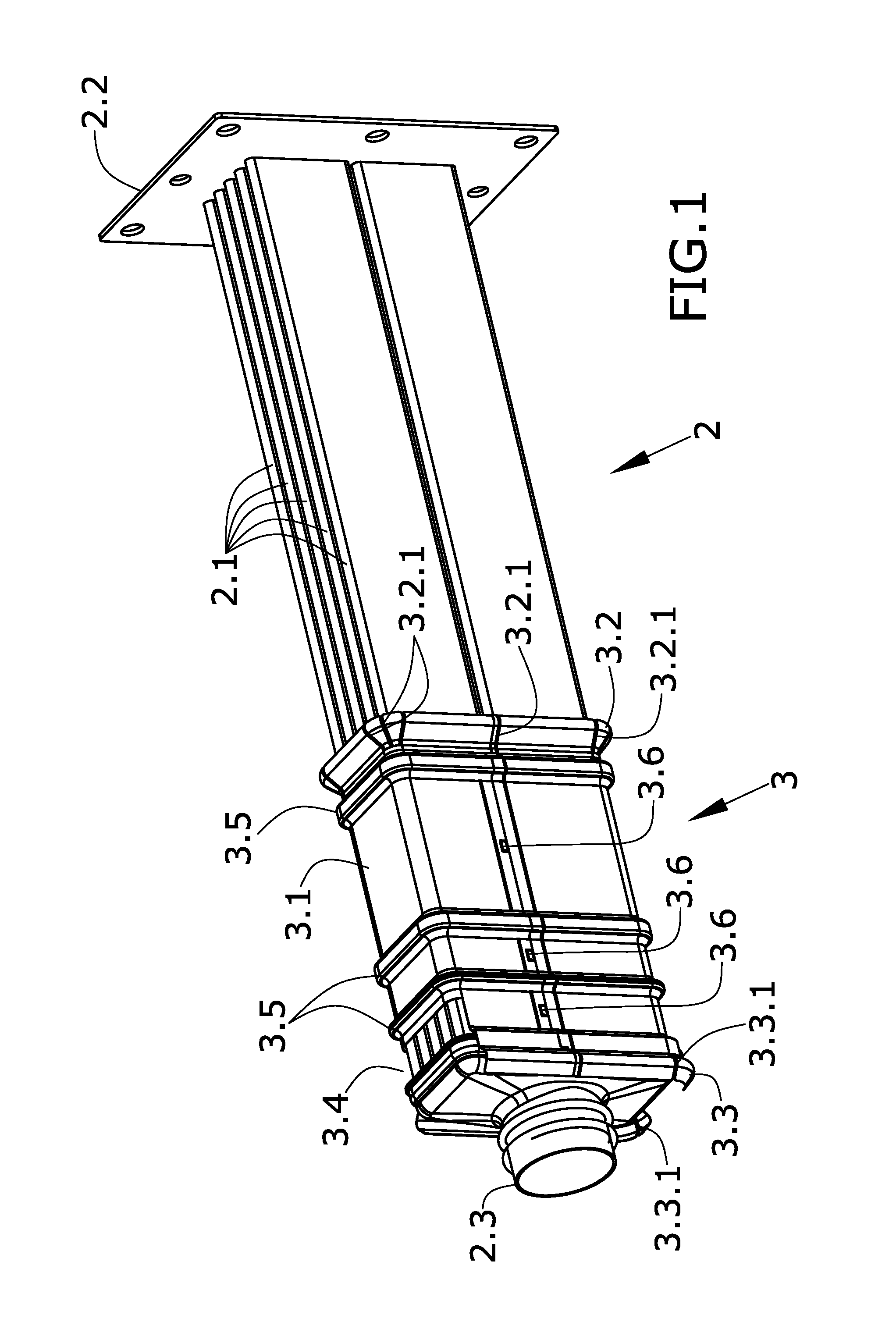
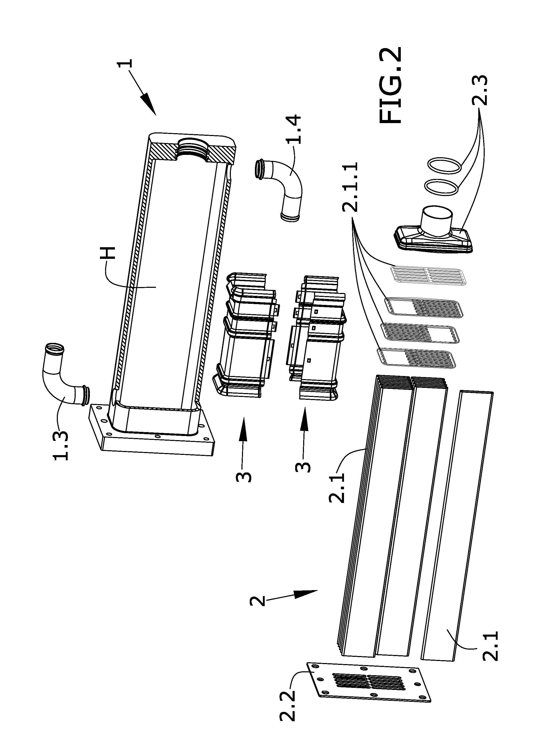
[0009]The present invention proposes a solution to the preceding problems by means of a flow deflection system.

[0010]A first inventive aspect provides a flow deflector adapted for being installed in heat exchangers of the type comprising a shell with an inner chamber through which a first coolant fluid circulates and where said shell houses at least a bundle of tubes through which a second fluid to be cooled circulates, where between the bundle of tubes and the wall of the inner chamber of the shell there is a perimetral gap in at least one section of the length of the bundle of tubes. The deflector according to this first inventive aspect comprises:

[0011]a tubular body adapted for surrounding at least one section of the length of the bundle of tubes,

[0012]a first expansion section arranged at one end of the tubular body such that the tubular body is extended longitudinally by means of the first expansion section where:

[0013]the first expansion section covers a larger perimeter than...


PUM


Abstract

The present invention relates to a device for deflecting coolant fluid flow in a heat exchanger, particularly a heat exchanger of an EGR (Exhaust Gas Recirculation) system, better cooling of the fluid to be cooled and flowing through the bundle of tubes of said heat exchanger being obtained.

Description

CROSS-REFERENCE TO RELATED APPLICATIONS[0001]This application claims the benefit of European Patent Application Serial No. EP14382234.4 filed Jun. 17, 2014.OBJECT OF THE INVENTION[0002]The present invention relates to a device for deflecting coolant fluid flow in a heat exchanger, particularly a heat exchanger of an EGR (Exhaust Gas Recirculation) system, better cooling of the fluid to be cooled and flowing through the bundle of tubes of said heat exchanger being obtained.BACKGROUND OF THE INVENTION[0003]Heat exchangers comprise bundles of tubes which are housed in a shell, and a flow channel of a first fluid, the coolant fluid, is generated in the space existing between said tubes and the shell. A second fluid cooled by the first fluid flowing through the outside of the tubes, removing heat by convection, circulates inside the tubes forming the bundle.[0004]Two types of spaces are distinguished in this heat exchanger configuration, i.e., the space existing between the tubes of the ...

Claims


Application Information

Patent Timeline
Patent Type & Authority Applications(United States)
IPC IPC(8): F28F13/08
CPCF28F13/08F28F9/005F28F9/22F28D7/1684F28D21/0003F28D2021/008F28F2265/10F02M26/32
Inventor GRANDE FERNANDEZ, JOSE ANTONIORODRIGUEZ TATO, MARCOS
Owner BORGWARNER EMISSIONS SYST SPAIN S L U
Learn More