Respirator with a circuit for breathing gas

a technology of breathing gas and circuit, which is applied in the direction of medical devices, lighting and heating apparatus, heating types, etc., can solve the problems of not being able to influence the control circuit, the exchanged amount of heat is not adapted to and the temperature of breathing gas is rising, etc., to achieve good thermal conductivity, reduce pressure, and improve the effect of cooling efficiency

Active Publication Date: 2010-05-06
DRAGER SAFETY
View PDF12 Cites 16 Cited by
  • Summary
  • Abstract
  • Description
  • Claims
  • Application Information

AI Technical Summary

Benefits of technology

[0011]An essential advantage of the present invention is the direct cooling of the breathing air in the breathing air duct of an air / air heat exchanger. As a result, cooling is more efficient than cooling via the outer surface of a lime absorber. The ergonomic requirements imposed on the closed-circuit gas mask and breathing equipment do not make it possible to use freely selectable geometric embodiments of the outer surface of the breathing lime absorber for the external cooling, so that an optimal thermal coupling of the largest possible number of breathing lime pellets in a narrow space with the outer surface of the breathing lime absorber is possible only conditionally. By contrast, nearly the entire amount of breathing gas circulating in a circuit can be cooled with a separate air / air heat exchanger. The air / air heat exchanger comprises a first inner duct for the breathing gas circuit and a second outer duct for the cooling gas circuit. The air in the cooling circuit is cooled down by means of the evaporative cooling by ambient air being caused to flow through the second duct by means of a gas delivery means and by a liquid evaporating agent being introduced into the second duct of the heat exchanger. The evaporating agent in the second duct is preferably introduced directly to the heat exchange surface between the first and second ducts.
[0012]A material possessing good thermal conductivity, for example, a metal, is preferably used as the material for the heat exchange surface.
[0013]The liquid evaporating agent is applied in the second duct directly onto the heat exchange surface by spray nozzles arranged in the second duct and is distributed there. As a result, the heat exchange surface is cooled directly, on the one hand, by the direct contact with the liquid evaporating agent, and, on the other hand, the air in the second duct of the air / air heat exchanger is cooled at a heat exchange surface due to the evaporation of the particles of evaporating agent.
[0014]An electrically driven positive displacement blower designed as a fan, which delivers a gas volume flow of preferably 150 L to 250 L per minute uniformly along the second duct of the heat exchanger in order to achieve evaporation of the evaporating agent, especially water, an aqueous solution or a mixture with water, which cools the air in the second duct, is used as a gas delivery means to deliver the air in the second duct in the simplest case. The amount of heat generated in the breathing lime absorber and contained in the breathing gas is removed in this manner to the outside as a result.
[0015]A gas volume flow of at least 150 L per minute has proved to be necessary to generate the amounts of convection air, which are different for the heat transport in the second duct. Both a parallel-flow heat exchanger and a counterflow heat exchanger may be used as the heat exchanger, the selection of the corresponding type being dependent on the dimensions in space of the closed-circuit gas mask and breathing equipment and the arrangement of the components gas delivery means, high-pressure oxygen cylinder, lime absorber, breathing bag and evaporating agent container in the closed-circuit gas mask and breathing equipment, which arrangement is dictated by the dimensions.
[0016]The evaporating agent, preferably water, can be provided in an evaporating agent container. The pressure of the oxygen cylinder, 200 bar, is brought to a working pressure of 5 bar by means of a pressure reducer. The pressure is then reduced further by means of a dispensing nozzle, so that oxygen is introduced into the breathing circuit at a rate ranging from 1 L / minute to 2 L / minute.

Problems solved by technology

The heat leads to a rise in the breathing gas temperature and may thus lead to a physical compromise for the person respirated by means of the respirator.
The exchanged amount of heat is thus not adapted to the breathing gas temperature and cannot be influenced by a control circuit.

Method used


Image

  • Respirator with a circuit for breathing gas
  • Respirator with a circuit for breathing gas
  • Respirator with a circuit for breathing gas

Examples


Embodiment Construction

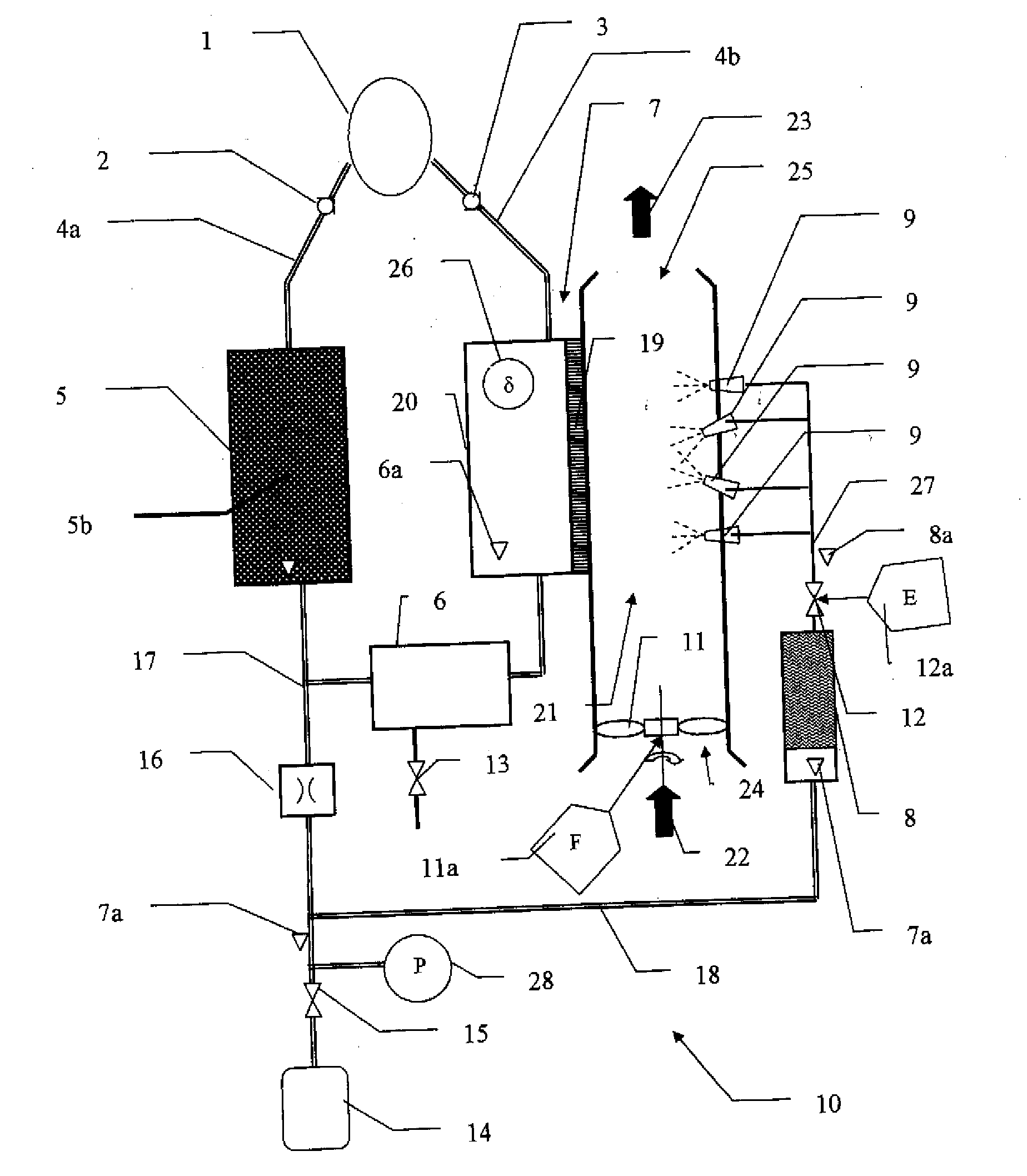
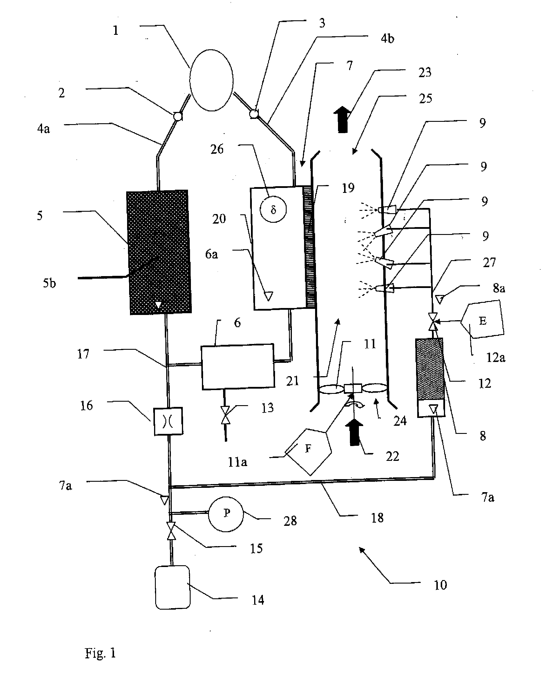
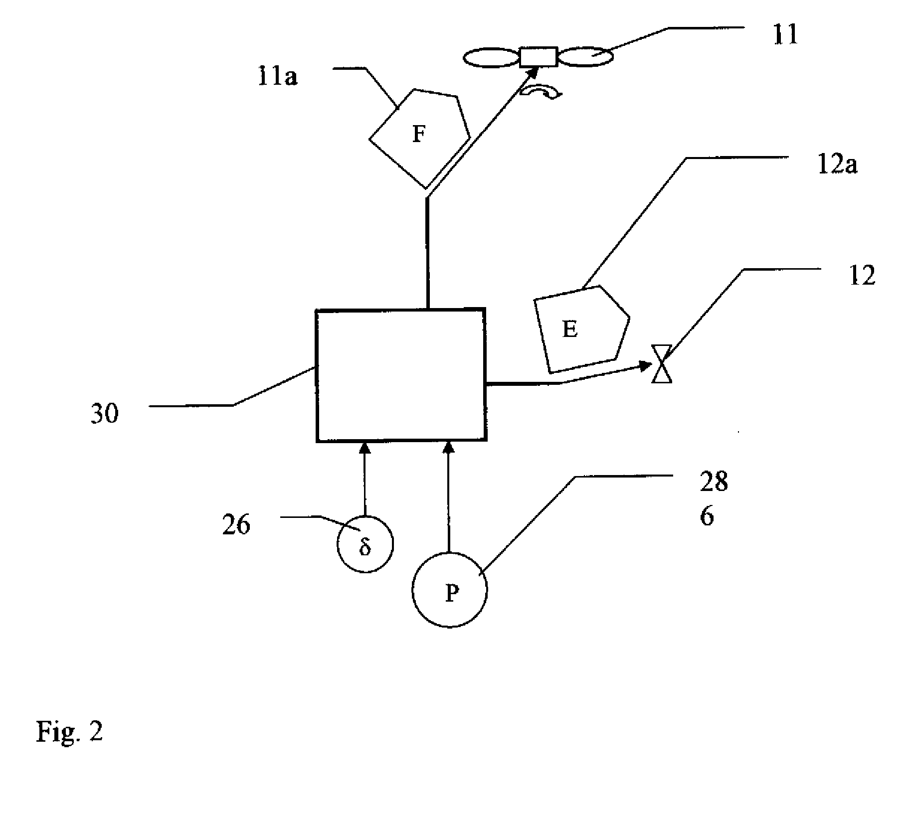
[0030]Referring to the drawings in particular, FIG. 1 shows a respirator housing 10, in which a breathing lime absorber 5, an air / air heat exchanger 7, an evaporating agent container 8, nonreturn valves 2, 3, a breathing bag 6, a group of spraying elements 9, a fan 11, an adjusting valve 12, a drain valve 13, a high-pressure oxygen cylinder 14, a pressure reducer 15, a dispensing nozzle 16, delivery lines 17, 18, and a temperature sensor 26 are arranged.

[0031]The expired air of the respirator user is released via the expiration breathing tube 4a and the nonreturn valve 2 to the breathing lime absorber 5. The user of the gas mask and breathing equipment again inspires via an inspiration breathing tube 4b and the nonreturn valve 3. The user inspires through the first duct 20 of the air / air heat exchanger from the breathing bag 6, which is connected to the breathing lime absorber 5. The circuit for the breathing gas is thus closed.

[0032]The gas from the high-pressure oxygen cylinder 14...


PUM


Abstract

A gas mask and breathing equipment is provided with a circuit for breathing gas and with a heat exchanger (7) cooled by an evaporating agent. The evaporating agent is introduced from an evaporating agent container (8) into the heat exchanger (7) via at least one group of spraying elements (9) and a gas delivery means (11) allows a gas volume flow to flow through the heat exchanger (7).

Description

CROSS REFERENCE TO RELATED APPLICATIONS[0001]This application claims the benefit of priority under 35 U.S.C. §119 of German Patent Application DE 10 2008 055 700.5 filed Nov. 3, 2008, the entire contents of which are incorporated herein by reference.FIELD OF THE INVENTION[0002]The present invention pertains to a device for cooling the breathing gas temperature in a respirator with a circuit for breathing gas and to a process for controlling the cooling of the respirator.BACKGROUND OF THE INVENTION[0003]In respirators, especially in gas masks and breathing equipment, respiration takes place in a closed circuit to reduce the weight and to increase the use time, and only the amount of oxygen consumed is replaced from a pressurized gas reservoir and fed into the circuit. Enrichment of the carbon dioxide (CO2) breathed out in the circuit to physiologically harmful levels in the circuit must be avoided. An absorber with an absorbent, which extracts the CO2 from the breathing circuit, is p...

Claims


Application Information

Patent Timeline
Patent Type & Authority Applications(United States)
IPC IPC(8): A61M16/00
CPCA61M16/1075A61M16/12A61M16/22A61M2205/3331A61M2205/3368A61M2205/3606A61M2205/362A61M2205/8218A62B7/00A62B9/00A62B9/003A61M2016/0027A61M16/0045
Inventor KOCH, JOCHIMPOLZIEN, JORG
Owner DRAGER SAFETY
Why Eureka
Try Eureka