

Permanent magnet embedded rotary electric machine
- Summary
- Abstract
- Description
- Claims
- Application Information
AI Technical Summary
Benefits of technology
Problems solved by technology
Method used
Image

Examples
first embodiment
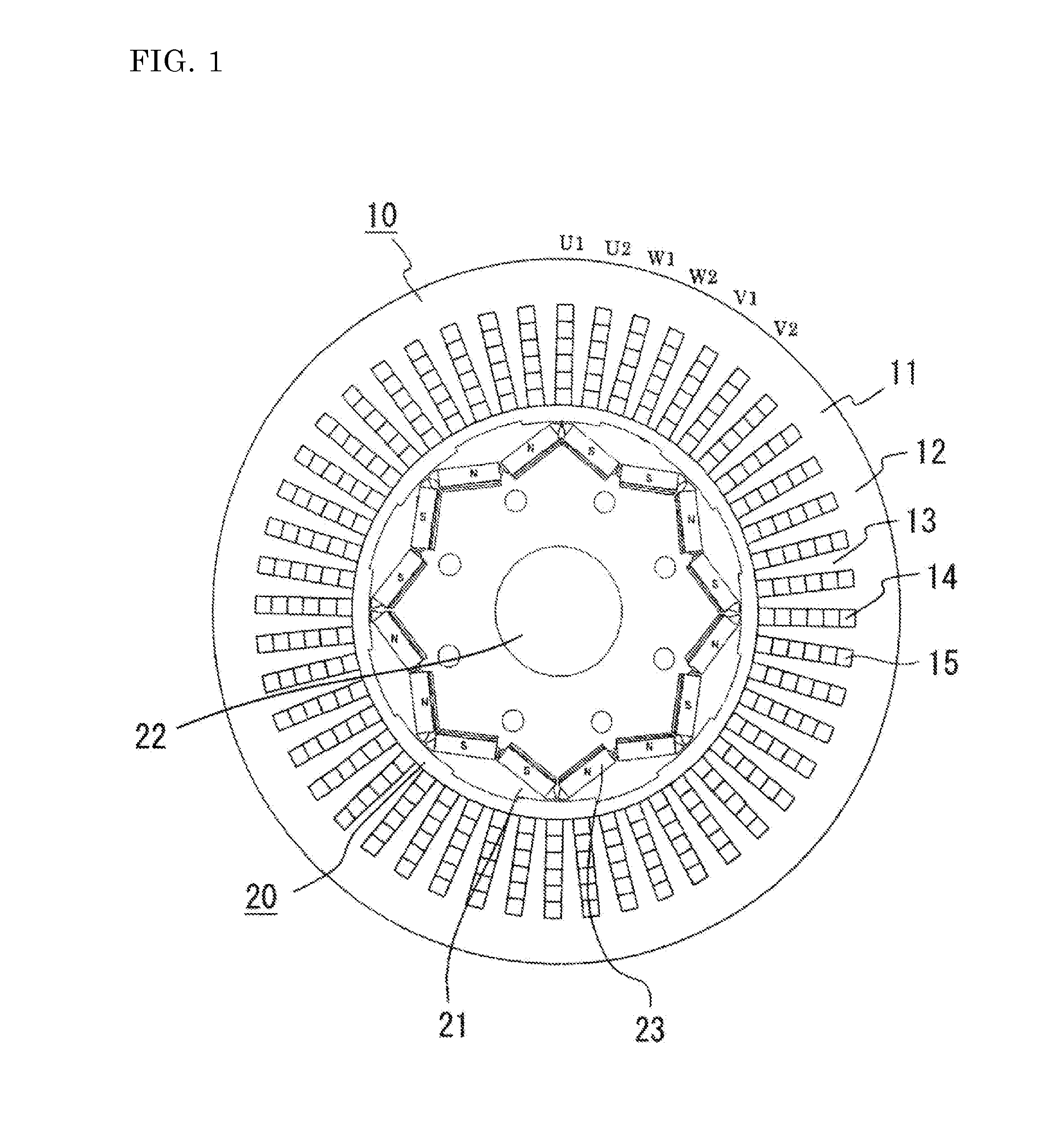
[0018]FIG. 1 is a side sectional view showing a permanent magnet embedded electric machine of the first embodiment of the present invention, showing an example in which planar permanent magnets are used and 16 poles and 48 slots are provided.
[0019]A stator 10 includes: a stator iron core 11 having a core back 12, teeth 13, and slots 14; and armature windings 15 for U1, U2, W1, W2, V1, and V2 which are wound in a distributed manner and provided in the slots 14.
[0020]U1, U2, W1, W2, V1, and V2 denote two pairs of three-phase armature windings 15. Specifically, a first U-phase winding is U1, a second U-phase winding is U2, a first V-phase winding is V1, a second V-phase winding is V2, a first W-phase winding is W1, and a second W-phase winding is W2.
[0021]U1, V1, and W1 constitute first armature windings, which are connected to a first inverter, and U2, V2, and W2 constitute second armature windings, which are connected to a second inverter.
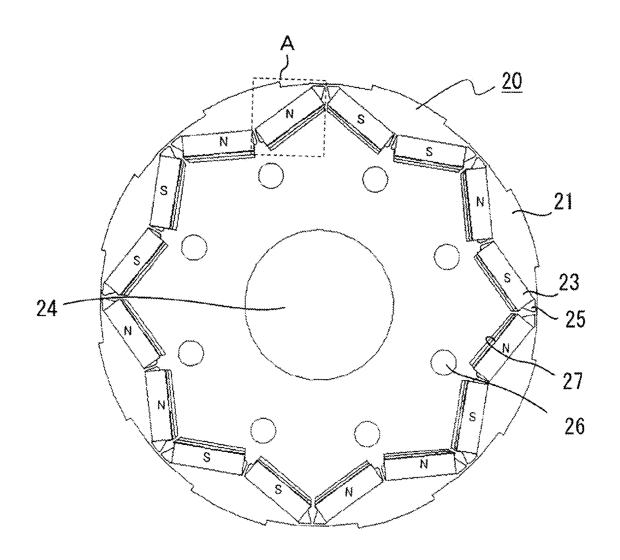
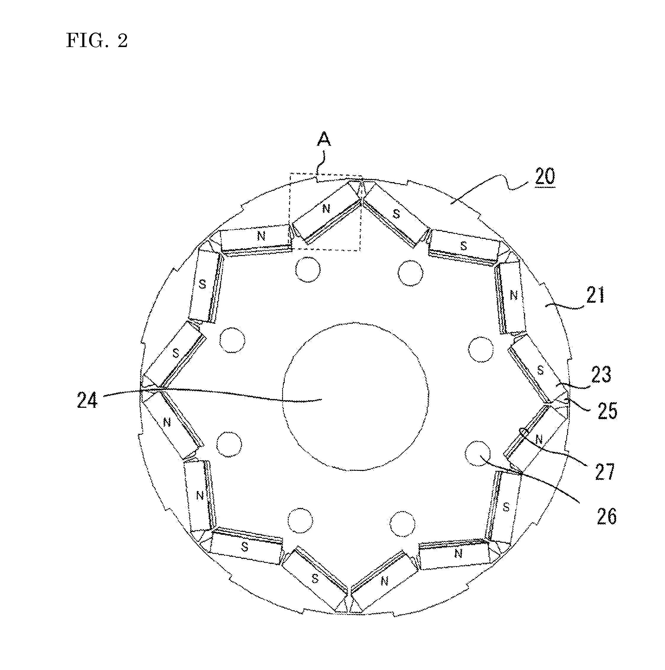
[0022]On the other hand, a rotor 20 includes:...
second embodiment
[0034]The above first embodiment shows the case where the plurality of protrusions 28 are provided in a direction perpendicular to a flowing direction of the cooling oil on the exposed portion 21a of the rotor iron core 21 in the refrigerant passage 27 under the permanent magnet. In the second embodiment, as shown in FIG. 6, on the exposed portion 21a of the rotor iron core 21 on which the refrigerant passage 27 is formed, the rotor iron core 21 itself forms the protrusions 28 by shaping the ends of the magnetic material sheets composing the rotor iron core 21 into a mountain-like shape.
[0035]Thus, in the refrigerant passage 27, the protrusions 28 can be formed by the rotor iron core itself. Therefore, as in the first embodiment, flow of the cooling oil passing through the refrigerant passage 27 shifts from laminar flow to turbulent flow when the cooling oil collides with the protrusions 28, whereby occurrence of a temperature boundary layer in the vicinity of the permanent magnet c...
third embodiment
[0036]In the above second embodiment, the protrusions 28 are formed by shaping the ends of the magnetic material sheets composing the rotor iron core 21. In the third embodiment, as shown in FIG. 7, shear droops 29 of the ends of the magnetic material sheets formed upon press working are located on the exposed portion 21a of the rotor iron core 21 on which the refrigerant passage 27 is formed, so that the shear droops 29 are utilized as the protrusions.
[0037]Thus, the magnetic material sheets obtained by press working can be directly used to form the protrusions 28 in the refrigerant passage 27. Therefore, as in the first and second embodiments, flow of the cooling oil passing through the refrigerant passage 27 shifts from laminar flow to turbulent flow when the cooling oil collides with the shear droops 29, whereby occurrence of a temperature boundary layer in the vicinity of the permanent magnet can be prevented, thus further enhancing the cooling effect for the permanent magnet 2...
PUM
 Abstract
Description
Claims
Application Information