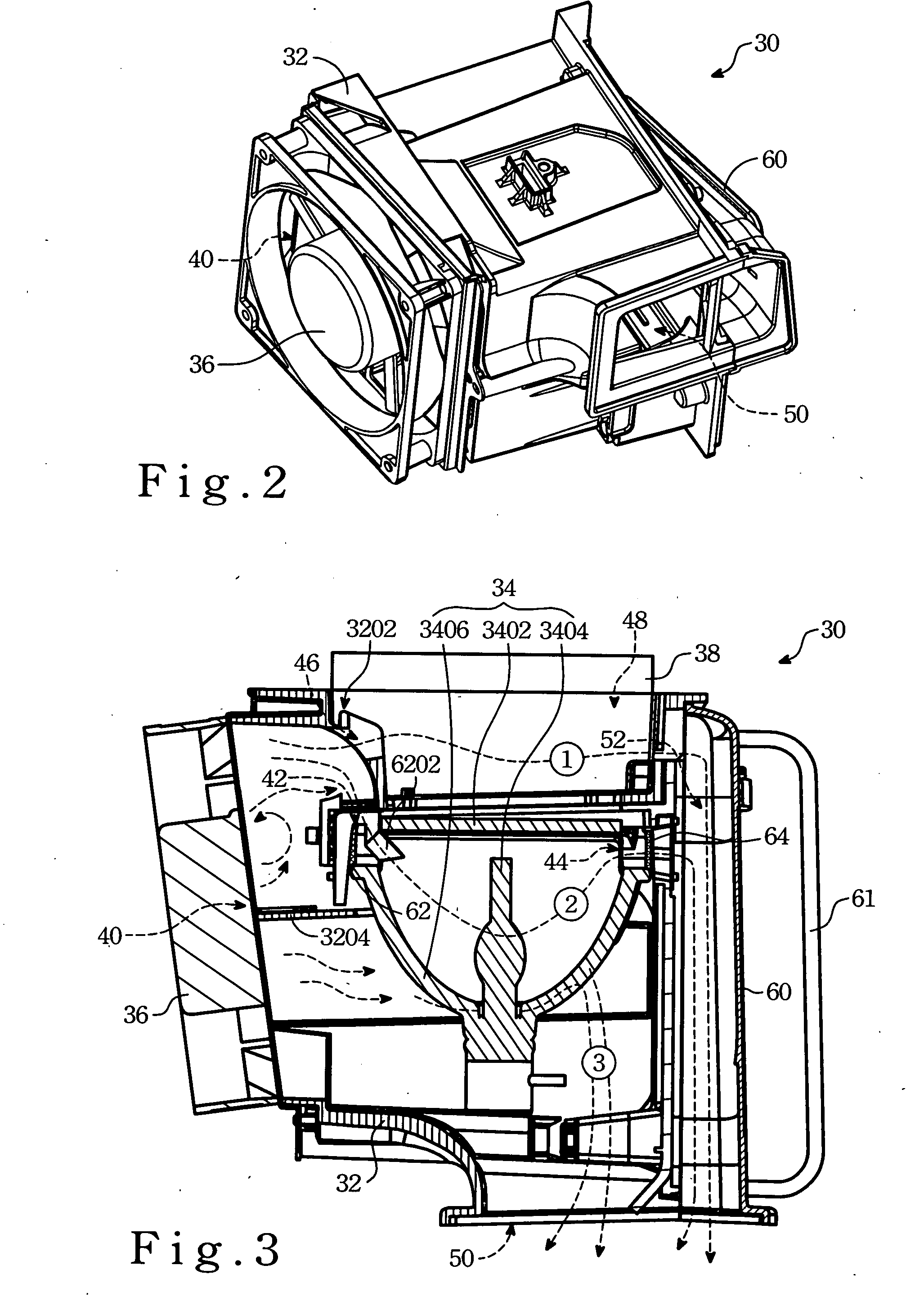
[0018]FIG. 2 is a perspective view of the heat-dissipating device 30 of the present invention and is used in a projection apparatus (not shown) in order to lower the intensive heat (temperature) caused by a lamp unit due to operation of the apparatus.
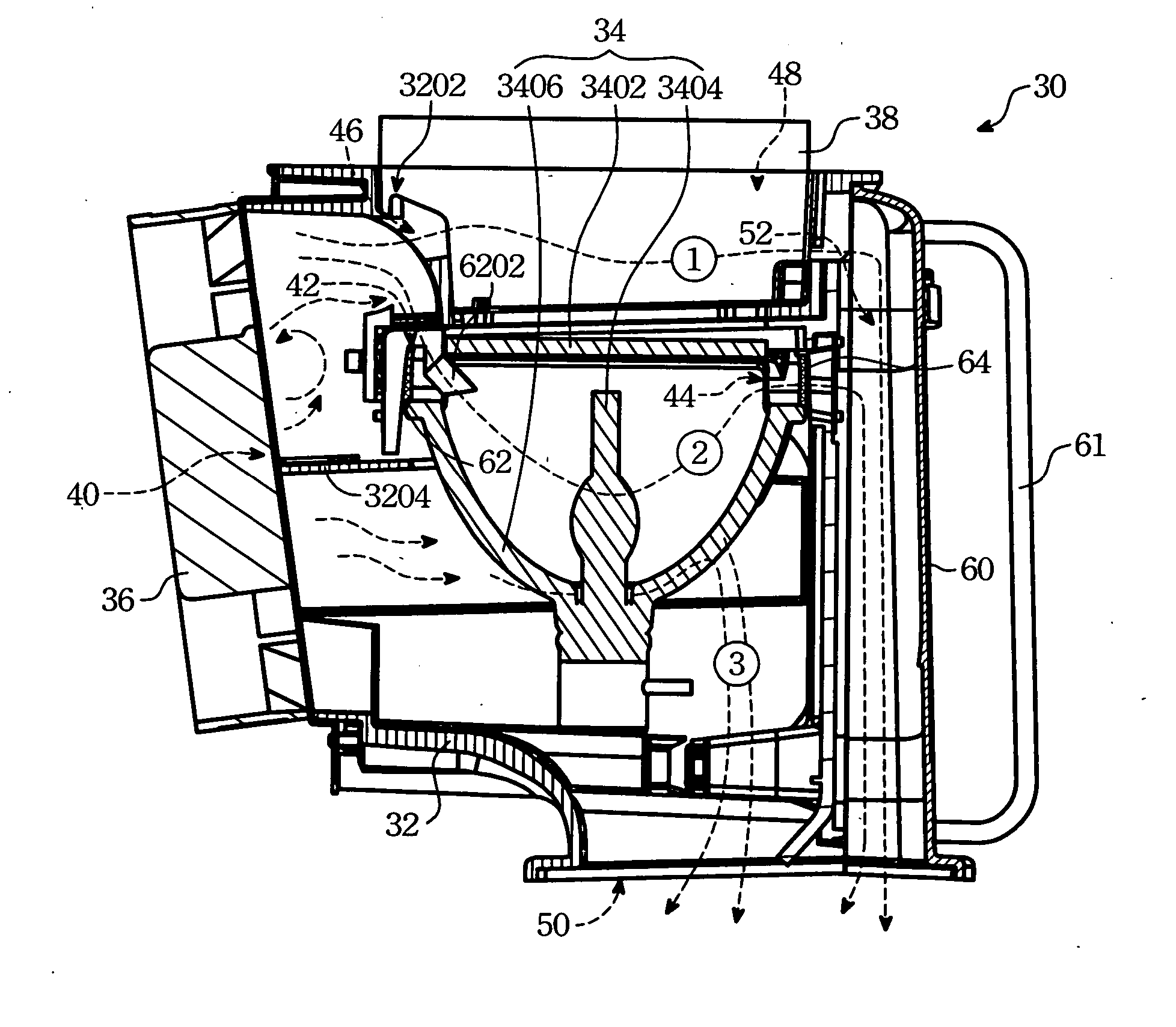
[0019]FIG. 3 is a top sectional view of the heat-dissipating device of the present invention, and includes a receptacle body 32, a lamp unit 34, a fan unit 36, a nozzle 3202 and an air guide partition 3204.
[0020] The receptacle body 32 has a lateral left wall formed with a left air vent 40. The lamp unit 34 is disposed in the receptacle body 32, and includes a burner 3404, a generally concave reflector 3406 surrounding the burner 3404, and a glass plate 3402 disposed in front of the reflector 3406. The reflector 3406 cooperates with the glass plate 3402 to define an air inlet 42 adjacent to the left air vent 40 and an air outlet 44 spaced from the left air vent 40.
[0021] The fan unit 36 (preferable an axial fan) is mounted on the receptacle body 32 for covering the left air vent 40 and for generating airflow to flow into the receptacle body 32 from the left air vent 40.
[0022]FIG. 4 is a bottom view illustrating an interior of the receptacle body 32 employed in the heat-dissipating device 30 of the present invention. Referring to FIG. 3, the nozzle 3202 is disposed within the receptacle body 32 between the left air vent 40 and the lamp unit 34, and is in spatial communication with the air inlet 42 for guiding air into the lamp unit 34. The nozzle 3202 has a guiding hole 46 at its intermediate portion thereof tending toward a front side of the glass plate 3402 for cooling the latter as well as the exterior of the lamp unit 34.
[0023] The receptacle body 32 further has a front wall formed with a front opening 48. A UV/IR filter 38 is fixed to the front wall of the receptacle body 32 in order to shield the front opening 48 in the receptacle body 32.
[0024] The air guide partition 3204 extends from the lateral left wall of the receptacle body 32 adjacent to the left air vent 40 toward the lamp unit 34, and is disposed behind the air inlet 42.
[0025] Note that rotation of the fan unit 36 results in airflow that is guided by the air guide partition 3204 and the nozzle 3202 toward the exterior of the glass plate 3402 and the interior of the reflector 3406, thereby lowering the ambient temperature around the lamp unit 34.
[0026] Referring again to FIG. 3, the receptacle body 32 has a lateral right wall that is disposed opposite to the lateral left wall and that is formed with a right air vent 52. An air-guiding pipe 60 is attached on the lateral right wall of the receptacle body 32, and extends from the right air vent 52 toward an exterior of the receptacle body 32. Preferably, a handgrip 61 is attached to the receptacle body 32 at the lateral right wall to facilitate insert or removal of the receptacle body 32 into and from the projection apparatus.
[0027] In addition, the receptacle body 32 further has a rear wall formed with a rear opening 50 for guiding the hot air to an exterior of the receptacle body 32.
[0028] In this embodiment, the air guiding pipe 60 has a first end integrally formed with a periphery confining the right air vent 52 and a second end terminating at a rear side of the reflector 3406 so as to guide the hot air from the front side of the reflector 3406 toward an exterior of the receptacle body 32 via the right air vent 52.
[0029]FIG. 5 is a top sectional view of a modified heat-dissipating device 30 of the present invention. In this embodiment, the receptacle body 32 has an upper wall formed with an upper opening 54. The air-guiding pipe 60 has a first end integrally formed with a periphery confining the right air vent 52 and a second end terminating at an upper side of the reflector 3406 so as to guide the hot air from the reflector 3406 toward an exterior of the. receptacle body 32 via the upper opening 54.
[0030] Referring to FIGS. 6 and 7, the heat-dissipating device 30 of the present invention further includes first and second protective nets 62, 64 disposed within the receptacle body 32 for covering the air inlet 42 and the air outlet 44 respectively from the exterior of the reflector 3406. Under this condition, in case there is an outburst of the burner 3404 within the reflector 3406, the broken pieces thereof are prevented from flying out of the receptacle body 32.
[0031] Note that in order to smooth flow of the airflow from the interior to the exterior of the reflector 3406, the criss-crossing strings for forming the protective nets 62, 64 are spaced apart from one another at a relatively large distance. However, such arrangement results in fly out of tiny broken pieces. In this embodiment, the second protective net 64 is preferably disposed transversely at the space adjoining the right air vent 52 and the air guiding pipe 60 so as to trap the broken pieces within the guiding pipe 60 in case of an outburst of the burner 3404.
[0032] The presence of first and second protective nets 62, 64 within the receptacle body 32 to protect the assembler or the user from being injured by the broken pieces during replacement of the lamp unit 34.
[0033] Preferably, a fin unit 6202 is provided in the receptacle body 32, and extending inwardly from the periphery confining the air inlet 42 toward the burner 3404 so as to enhance the reduction of the temperature of the burner 3404.
[0034] To summarize the above paragraphs, it is observable that employment of the heat-dissipation device 30 of the present invention in the projection apparatus, the cooling effect of the projection apparatus is enhanced. The apparatus is constructed in the compact size since the single fan unit occupies a relatively small space in the receptacle body. The presence of the protective nets 62, 64 in the receptacle body 32 provides a profound safety to the assembler or the user of the projection apparatus.
[0035] While the present invention has been described in connection with what is considered the most practical and preferred embodiments, it is understood that this invention is not limited to the disclosed embodiments but is intended to cover various arrangements included within the spirit and scope of the broadest interpretation so as to encompass all such modifications and equivalent arrangements.