
Method for installing LED light bar into light bulb and device

Active Publication Date: 2018-04-26
XIAMEN ECO LIGHTING CO LTD
View PDF16 Cites 3 Cited by
  • Summary
  • Abstract
  • Description
  • Claims
  • Application Information

AI Technical Summary

Benefits of technology

The patent describes a new LED light bulb design that improves cooling and lighting. The bulb has LED light bars that are positioned close to the inner wall of the bulb shell, either directly or by expanding along the inner wall. This helps to increase the heat dissipation effect and improve the cooling of the LED light bars. The bulb has a relatively narrow neck portion, which allows the LED light bars to be close to the shell and cool better. Overall, this design improves the performance and lifespan of the LED light bulb.

Problems solved by technology

In addition, the manufacturing cost of the light emitted diodes decreased continually with the manufacturing technology improvement.
If there is no effective way to remove these heat, it often will affect the service life of the lighting device itself.
In addition, how to effectively improve the location and angle for light emitted diode to emit light, will also affect the real lighting efficiency of the lighting device.

Method used


Image

  • Method for installing LED light bar into light bulb and device
  • Method for installing LED light bar into light bulb and device
  • Method for installing LED light bar into light bulb and device

Examples


Embodiment Construction

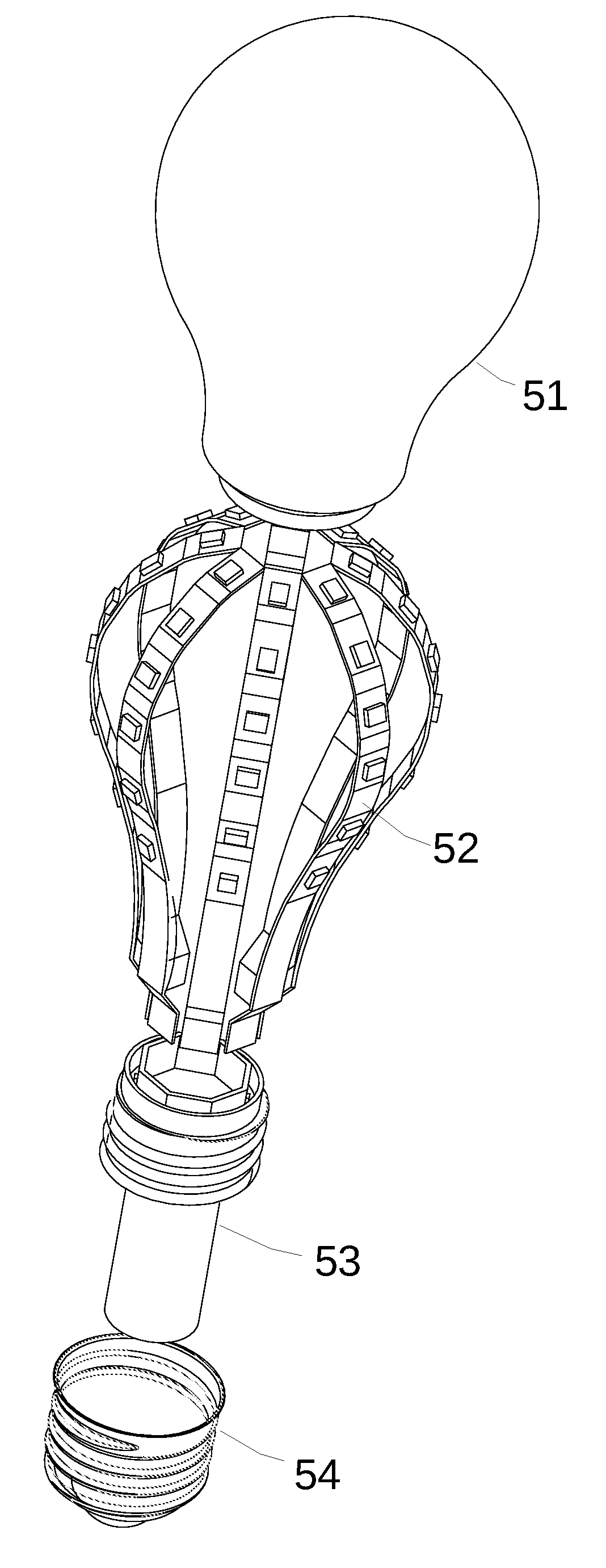
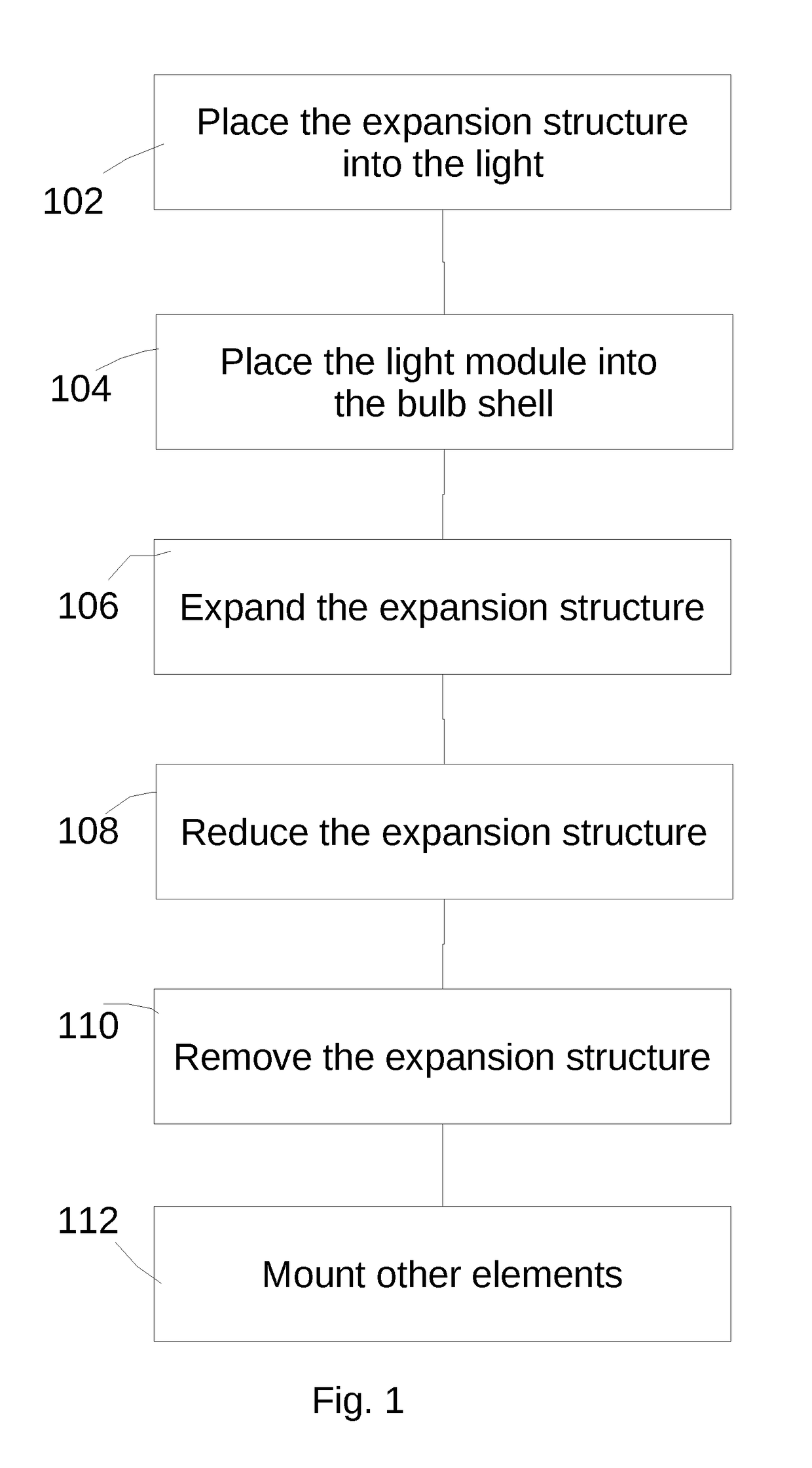
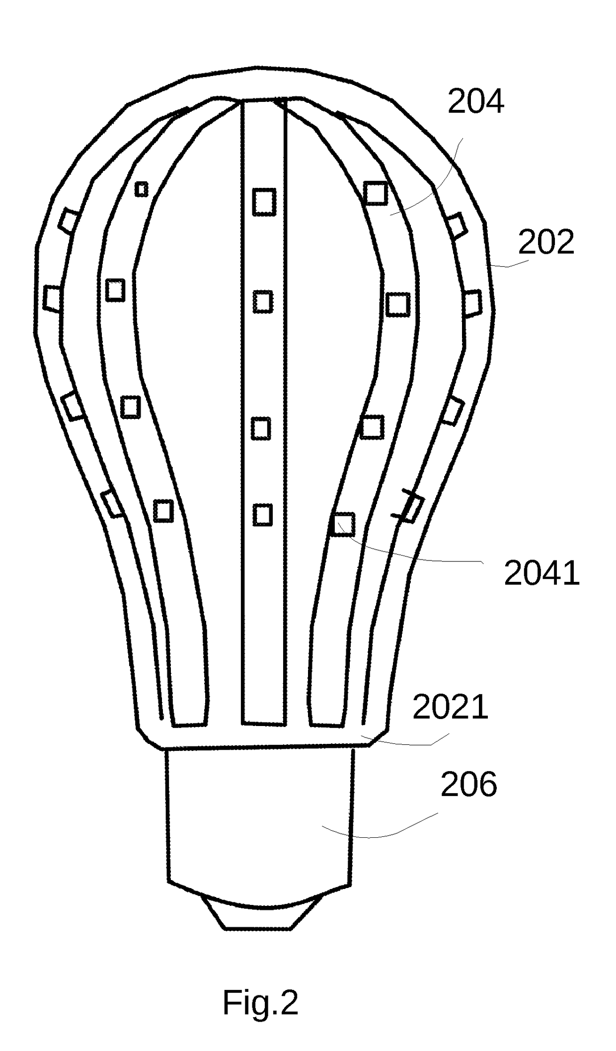
[0055]Please refer to FIG. 1. FIG. 1 illustrates a method of assembling a bulb device according to an embodiment of the present disclosure. According to the first embodiment of the present invention, a method of mounting a LED light bar in a bulb is provided. First, place the expansion structure into the light module (step 102). Second, place the light module into the bulb shell (step 104). The shape of bulb shell could be traditional bulb type, candle bulb shell type, flat-head type, polygonal shape, special shape or other shapes. The bulb shell has a certain degree of translucent, so the light will be emitted out from the surface of the bulb when placed the light emitted device into the bulb. The surface of the bulb shell could be fully transparent, partly translucent, atomized, smooth or rough shell. The material of the bulb shell may be glass, plastic, or other light translucent material.

[0056]In some common bulb cases, there is often a neck portion with a relatively small diame...


PUM


Abstract

A method for installing a LED light bar into a light bulb. First, place a light module into bulb shell. The light bar module has a plurality of LED light bars and expansion structure. The expansion structure is unexpanded and disposed between the plurality of LED light bars. Each LED light bar has a certain bending property. Expending the expansion structure could make the plurality of LED light bars bent to the direction of bulb shell individually. And then, remove the expansion module and install the other components of the bulb.

Description

FIELD OF THE INVENTION[0001]The present disclosure relates to a method for installing a light bar into a light bulb and bulb device and lighting device by the same, and more particularly to a method for installing a light emitted diode light bar into a light bulb and bulb device and lighting device by the same.BACKGROUND OF INVENTION[0002]Lighting is an important part of human life, and plays an increasingly important role. With the evolution and development of technology, the technology of light emitted diode is widely used in daily lighting device. The luminous efficiency of light emitted diode is usually higher than the traditional tungsten or fluorescent lamps. In addition, the manufacturing cost of the light emitted diodes decreased continually with the manufacturing technology improvement. This has led to more people developing more light emitted diode lighting devices.[0003]On the other hand, although the luminous efficiency of light emitted diode is quite high, either the dr...

Claims


Application Information

Patent Timeline
IPC IPC(8): F21K9/237F21K9/238F21K9/232F21V3/02F21V23/06F21V17/10F21V29/89
CPCF21K9/237F21K9/238F21K9/232F21V29/89F21V23/06F21V17/101F21V3/02F21K9/90F21V19/002F21Y2115/10F21Y2107/70
Inventor CAO, LIANGLIANGSU, LILEILI, WANZHEN
Owner XIAMEN ECO LIGHTING CO LTD
Learn More