Heat dissipating system using fans

Inactive Publication Date: 2015-09-17
MINGSHUO COMP (SUZHOU) CO LTD +1
View PDF5 Cites 9 Cited by
  • Summary
  • Abstract
  • Description
  • Claims
  • Application Information

AI Technical Summary

Benefits of technology

[0018]To sum up, the heat dissipating system using fans of the invention has a dual-fan design. When the computation amount of the electronic device does not exceed a specific amount, i.e., when the temperature of the electronic device is lower than a predeter

Problems solved by technology

When the computation amount of the processor becomes larger, it is difficult to use one fan to meet the heat dissipation requirement of the system.
However, the design of these electronic devices w

Method used


Image

  • Heat dissipating system using fans
  • Heat dissipating system using fans
  • Heat dissipating system using fans

Examples


Example

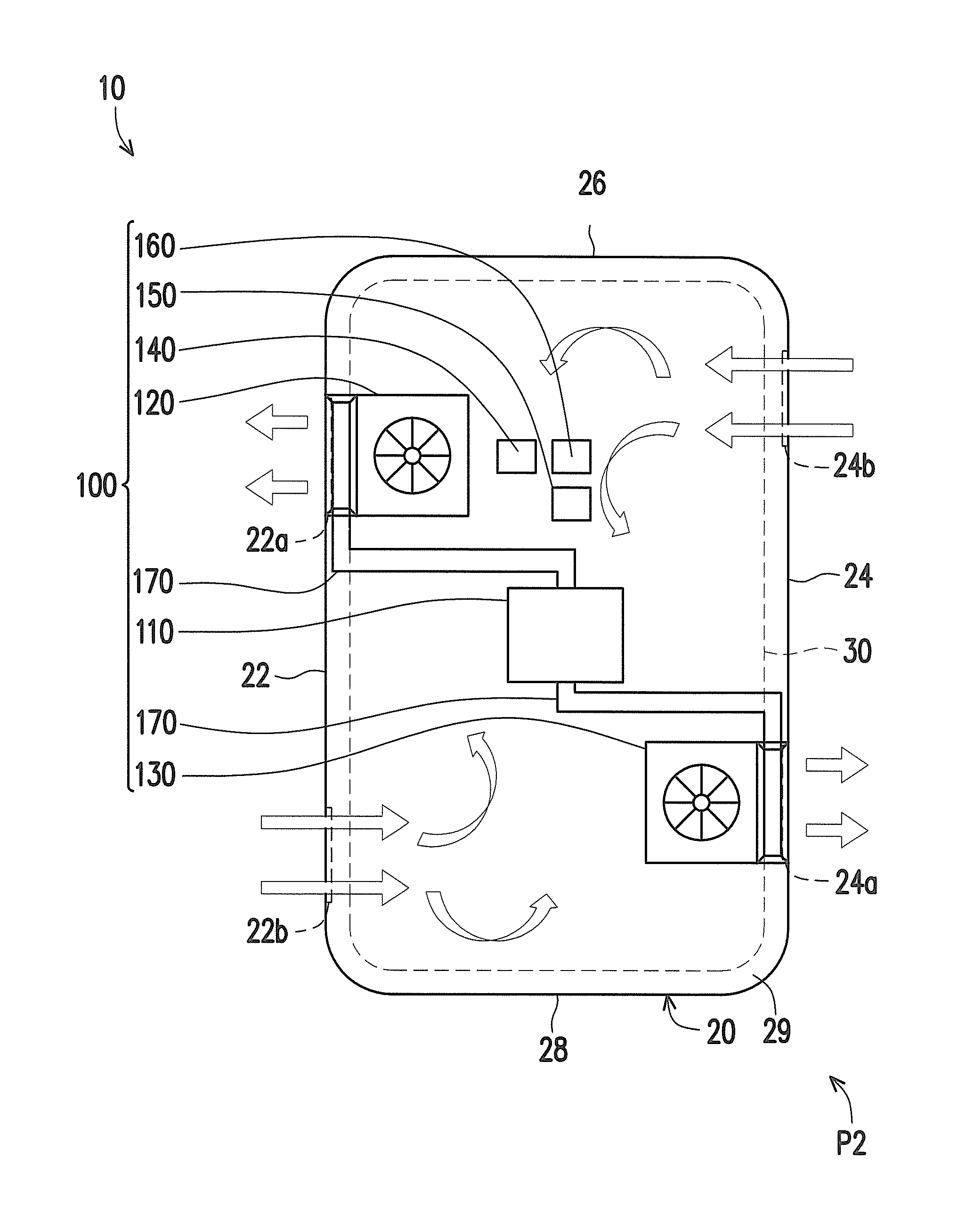
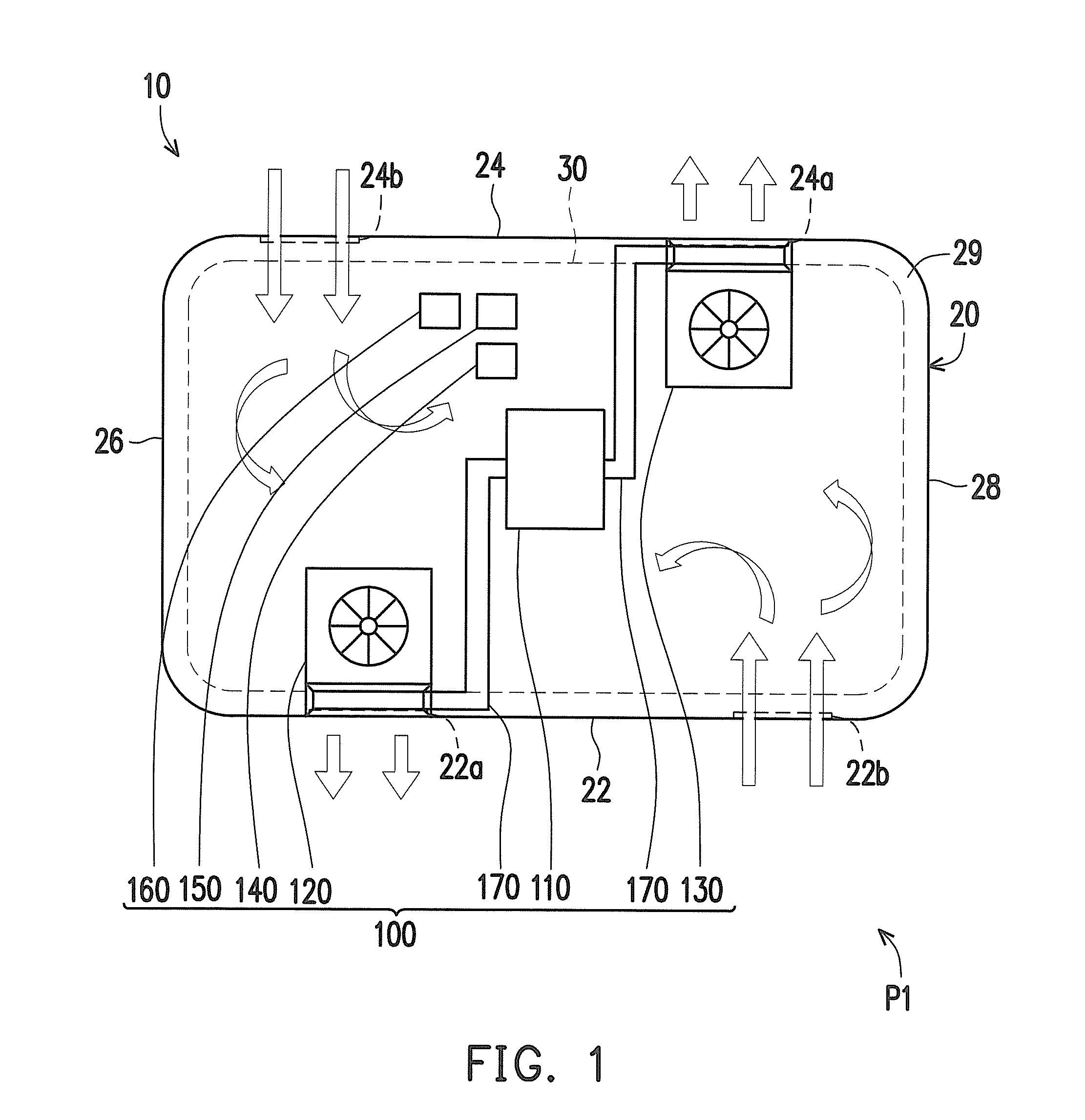
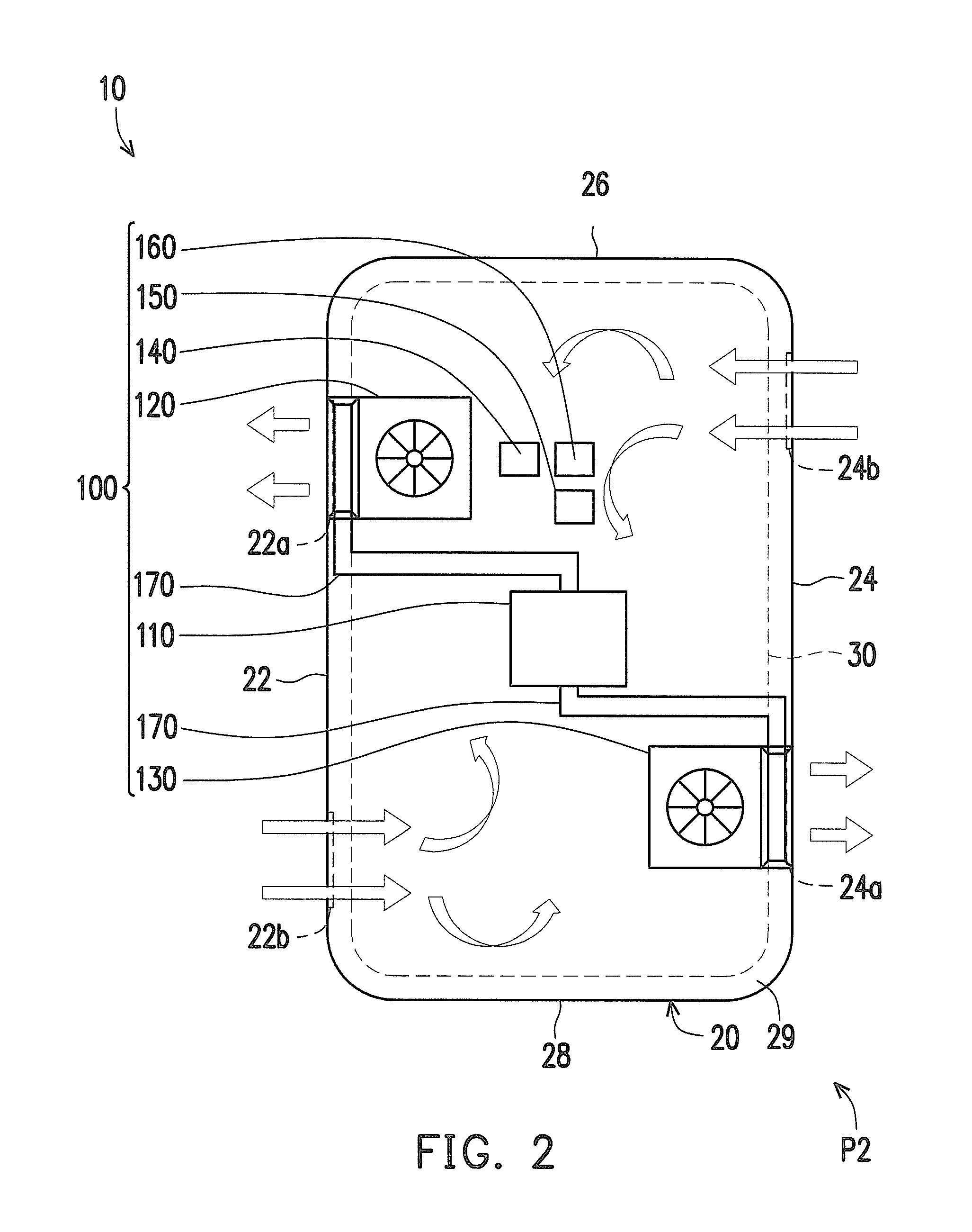
[0024]FIG. 1 is a schematic diagram showing an electronic device having a heat dissipating system using fans according to an embodiment of the invention. Referring to FIG. 1, a heat dissipating system using fans 100 is for an electronic device 10. In the present embodiment, the electronic device 10 may be a tablet computer for example. However, in other embodiments, the electronic device may be other device that can be placed vertically or horizontally.

[0025]The electronic device 10 includes a housing 20 and a touch panel 30. The housing 20 includes a first side surface 22 and a second side surface 24 opposite to each other, a third side surface 26 and a fourth side surface 28 opposite to each other, and a front surface 29 connected with the first side surface 22, the second side surface 24, the third side surface 26, and the fourth side surface 28. The touch panel 30 is disposed at the front surface 29 of the housing 20 (to show the relationship between the heat dissipating system ...


PUM


Abstract

This disclosure discloses a heat dissipating system using fans for an electronic device. The electronic device includes a first air outlet and a second air outlet. The heat dissipating system using fans includes a processor, a first fan, a second fan, an orientation sensor, and a temperature sensor. The orientation sensor is for sensing whether the electronic device is under a horizontal state or a vertical state and generating a corresponding orientation signal. The temperature sensor is for sensing the temperature of the electronic device and generating a temperature signal. When the temperature signal is greater than or equal to a predetermined value, the processor activates the first fan and the second fan. When the temperature signal is less than the predetermined value, the processor selectively activates one of the first fan and the second fan according to handedness information and the orientation signal.

Description


Claims


Application Information

Patent Timeline
Owner MINGSHUO COMP (SUZHOU) CO LTD
Why Eureka
Try Eureka