This helps you quickly interpret patents by identifying the three key elements:
Problems solved by technology
Method used
Benefits of technology
[0028]The importance stems from the amount of space needed to allow the reflector to bounce light back past the tubes and toward the TIA, and also the space needed for dissipation of heat. Convection allows cool air to be drawn past the fins and dissipating heat will protect the ballast. The compact fluorescent floodlight has a lens designed to precisely control the light from the reflector. It is covered with small, detailed shapes to direct the light into the desired beam pattern. The lens also acts as a cover to allow the lamp to act as it own fixture.
[0029]A second embodiment of applicant's invention employs an “implant” consisting of a spirally configured fluorescent or compact fluorescent lamp which is fitted with a reflective surface proximate to the interior portion of the lamp itself. This implant may be retrofitted into a conventional high-bay industrial fixture, thereby delivering an equivalent amount of light to the TIA with less wattage consumed. Each spiral lamp has proximate to it a primary reflector to re-direct light which might otherwise be “lost,” meaning not directed to the TIA, and as well, a secondary reflector which helps direct the light to a third reflector which finally directs the focused light to the TIA.
[0030]A third embodiment of applicants invention employs a high intensity disc
Problems solved by technology
Many industrial and commercial buildings have the burden of illuminating large areas from standard height as well as from higher than normal ceilings.
Mercury vapor, sodium and other high intensity discharge lamps in commercial applications may consume as much as 400 to 1000 watts, and generate an associated amount of heat, contributing to additional heating, ventilating and air conditioning (“HVAC”) operation and fire protection consideration
Method used
Image
Click on the blue label to locate the original text in one second.
Reading with bidirectional positioning of images and text.
Examples
Embodiment Construction
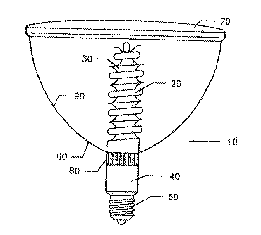
[0088]As seen in FIG. 1, a flood light 10 comprises a spiral compact fluorescent lamp 20 around which a primary reflector 30 is positioned. A first bonding means, such as glue or other adhesive or mechanical means is employed to fix lamp 20 and primary reflector 30 in a predetermined position. Lamp 20 is constructed in accordance with typical fluorescent lamps, comprising phosphor coating applied to the inside of the tube with hot cathodes at each end of the lamp. Air is exhausted through the exhaust tube during manufacture and an inert gas is introduced into the bulb. A minute quantity of liquid mercury is included with gas, the gas is usually argon. The stem press has lead-in-wires connecting the base pins and carry the current to and from the cathodes and the mercury arc. Reflector 30 may be fashioned from a variety of materials including but not limited to chrome-plated glass, chrome-plated metal, polished or painted aluminum plate, painted glass, and painted plastic with a vari...
PUM
Abstract
A lighting apparatus including a reflector having a reflective surface partially enclosing an interior space and defining a focal point within the interior space, and a filament positioned substantially within the interior space. In some examples, the filament is made substantially of tungsten. In some examples, the reflective surface extends along a longitudinal axis and curves around the longitudinal axis. In some examples, the reflective surface defines an elliptical paraboloid. In some examples, the filament may be placed substantially at the focal point of the reflective surface.
Description
CROSS-REFERENCE TO RELATED APPLICATIONS[0001]This application is a continuation-in-part of, and claims priority to, copending applications:[0002]Ser. No. 12 / 768,717, filed Apr. 27, 2010;[0003]Ser. No. 12 / 717,051, filed Mar. 3, 2010;[0004]Ser. No. 12 / 070,712, now U.S. Patent Application Pub. No. 2008 / 0232109, filed Feb. 19, 2008;[0005]Ser. No. 11 / 588,959, filed on Oct. 27, 2006, now U.S. Pat. No. 7,390,106; and[0006]Ser. No. 10 / 393,816, filed on Mar. 21, 2003, now U.S. Pat. No. 7,178,944.The disclosures of the cited related applications are incorporated herein by reference in their entirety for all purposes.FIELD OF THE INVENTION[0007]The instant invention may be considered to be in the field of lighting devices, specifically lamps of high intensity discharge and fluorescent lamps, but not limited thereto.BACKGROUND OF INVENTION[0008]Many industrial and commercial buildings have the burden of illuminating large areas from standard height as well as from higher than normal ceilings. O...
Claims
Application Information
Patent Timeline
Application Date:The date an application was filed.
Publication Date:The date a patent or application was officially published.
First Publication Date:The earliest publication date of a patent with the same application number.
Issue Date:Publication date of the patent grant document.
PCT Entry Date:The Entry date of PCT National Phase.
Estimated Expiry Date:The statutory expiry date of a patent right according to the Patent Law, and it is the longest term of protection that the patent right can achieve without the termination of the patent right due to other reasons(Term extension factor has been taken into account ).
Invalid Date:Actual expiry date is based on effective date or publication date of legal transaction data of invalid patent.