Shield casing with heat sink for electric circuits

Inactive Publication Date: 2005-01-27
THOMSON LICENSING SA
View PDF2 Cites 10 Cited by
  • Summary
  • Abstract
  • Description
  • Claims
  • Application Information

AI Technical Summary

Benefits of technology

[0008] To achieve this object a shield casing is suggested having no unwanted openings, thus providing good shielding against EMI phenomena, and having means for thermally contacting heat generating components inside the casing, using the casing as a heat sink to dissipate heat. The suggested shield casing consists of at least a frame, a cover and an inwardly projecting element for thermally contacting a heat source within the casing, according to claim 1. The inwardly projecting element is designed so as not to cause any unwanted openings in the casing. Advantageous embodiments of the invention are disclosed in the sub claims.
[0009] According to the invention, the shield casing has an element projecting inwards into the space confined by a frame and a lid, the element contacting a heat source inside the casing and serving as a thermal conductor. In a preferred embodiment the inwardly projecting element is attached to the frame near the top rim of the frame. It is, however, possible that the inwardly projecting element is attached to the lower rim of the frame. Depending on the number of heat-generating components inside the shield casing one or more inwardly projecting elements may be used. In a preferred embodiment the frame is a cut-and-bent part, which is produced by cutting a planar material, e.g., sheet metal, and bending the cut piece into its desired three-dimensional form. In this way the frame can be produced from one single piece. It is, however, possible to produce the frame using other techniques, such as die casting, or to assemble the frame from multiple parts using soldering or welding techniques, riveting or interlocking parts, a method also known to the public as snap-together. The inwardly projecting element is bent in a way, that a plane surface of the element resiliently contacts a corresponding s

Problems solved by technology

Electric and electronic circuits are often subject to electromagnetic interference caused by other circuits in the vicinity, nearby conductors carrying high frequency signals or large currents, or other sources.
Especially, circuits for receiving high frequency signals having low signal levels are subject to EMI.
However, the circuitry inside the shield casing, especially active semiconductor components, may generate considerable heat, which has to be dissipated in ord

Method used


Image

  • Shield casing with heat sink for electric circuits
  • Shield casing with heat sink for electric circuits
  • Shield casing with heat sink for electric circuits

Examples


first embodiment

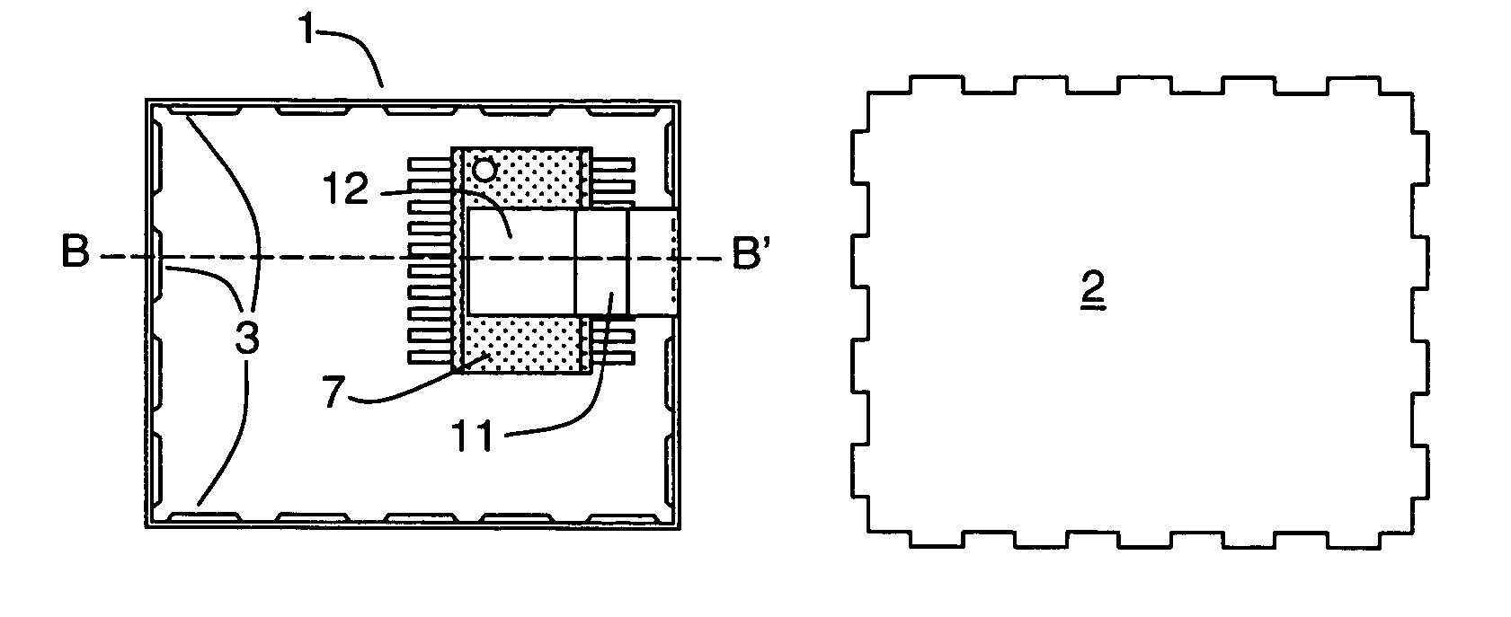
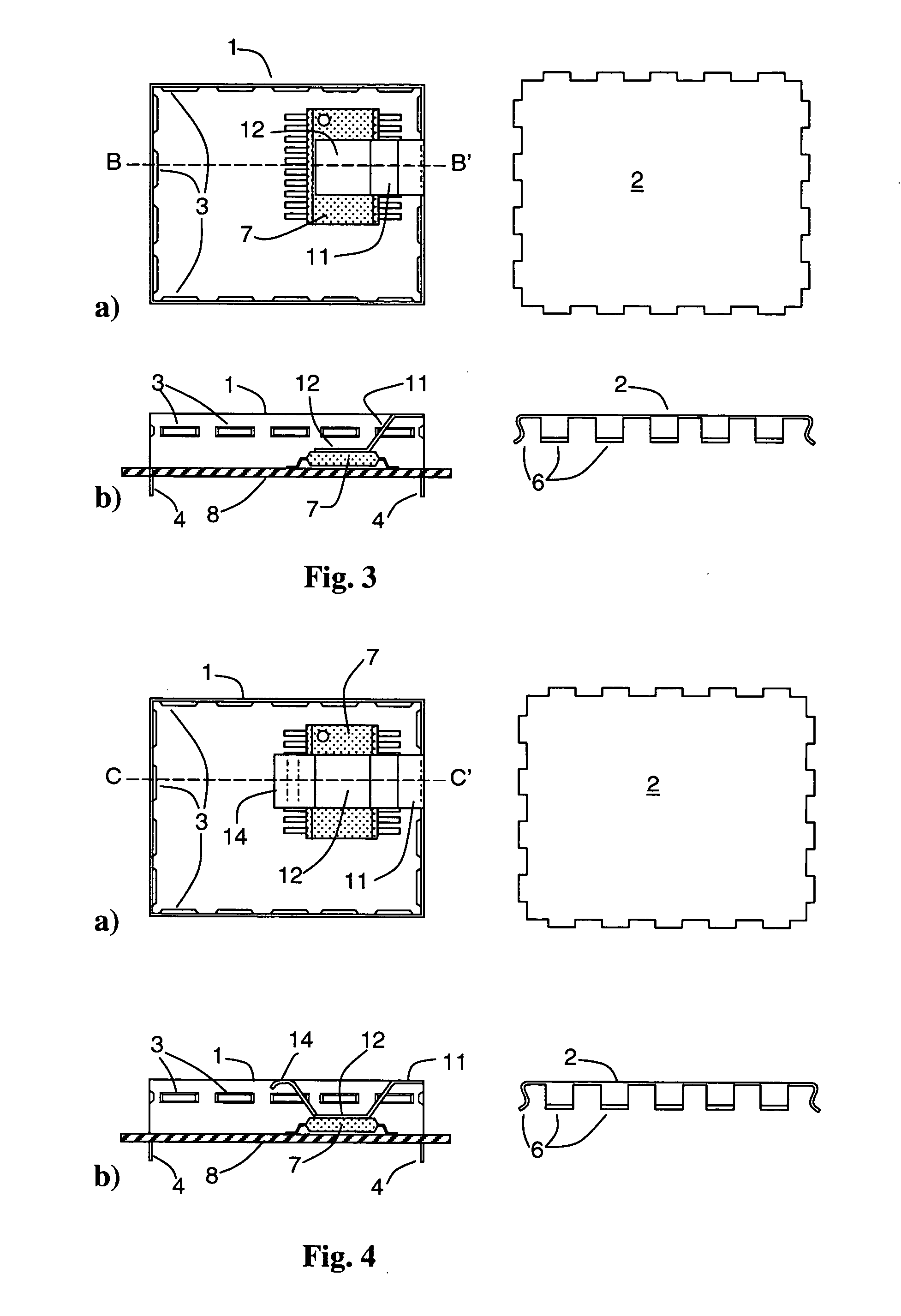
[0018]FIG. 3 shows a shield casing according to the invention. The left side of FIG. 3a) shows a top view of a frame 1 with a thermal conductor 11. A heat source 7 is represented by a schematic view of an integrated circuit. An area of contact 12 of the thermal conductor 11 thermally contacts a corresponding surface of the heat source 7. Depressed parts 3 are arranged along the circumference of the frame, serving as engaging elements for corresponding parts of a lid. The right side of FIG. 3a) shows a top view of a lid 2, which obviously has no openings caused by a thermal conductor, thus ensuring proper shielding when mounted to the frame 1. FIG. 3b) shows in its left side a side view of the frame 1 cut along a section line B-B′ shown in FIG. 3a). The frame 1 is mounted to a circuit carrier 8, which carries the heat source 7, by means of projecting elements 4. The thermal conductor 11 is bent inwards from the top right rim of the frame 1. The thermal conductor 11 is bent in a way, ...

second embodiment

[0019]FIG. 4 shows a shield frame according to the invention. On the left side of FIG. 4a) a top view of a frame 1 is shown. As previously described in FIG. 3, the frame bears a thermal conductor 11, attached to the upper right rim of the frame 1. The thermal conductor 11 has an area of contact 12 for contacting a corresponding surface of a heat source 7. The heat source 7 is represented by a schematic view of an integrated circuit. The free end or support section 14 of the thermal conductor 11 is bent towards a lid 2, which is shown on the right side of FIG. 4a), and the correctly placed lid 2 applies a force on the support section 14, increasing the pressure between the area of contact 12 and the corresponding surface of the heat source 7. Like before, depressed parts 3 serve as an interlocking element for securing the lid 2. The lid 2 is essentially of the same kind as the one described in FIG. 3. The function of the support section 14 of thermal conductor 11 is easier understood...

third embodiment

[0020]FIG. 5 shows a shield casing according to the invention. FIG. 5a) shows on its left side a top view of a frame 1 with depressed parts 3 along its circumference. Like in the embodiments described before, the depressed parts 3 serve as interlocking elements for corresponding elements of a lid 2, which is shown on the right side of FIG. 5a). The lid 2 has a thermal conductor 11 attached to it on its right side. The thermal conductor 11 is bent downward underneath the lid 2 and has an area of contact 12 for contacting a corresponding surface of a heat sink. The thermal conductor further has a support section 14, which is bent upward against the lid 2 and applies an additional force on the area of contact. The function is easier to be understood taking a look at FIG. 5b). FIG. 5b) shows on its left side a side view of the frame 1 with depressed parts 3 for electrically and mechanically contacting the lid 2 and projecting elements 4 for mounting the frame to a circuit carrier 8. On ...


PUM


Abstract

A casing for electric circuits is proposed, which shields the circuits from EMI phenomena. The circuit has means for making thermal contact with heat generating components inside the casing, allowing using the casing as a heat sink to dissipate the heat. The casing comprises a frame, a cover and an inwardly projecting element for thermally contacting a heat source within the casing. The inwardly projecting element is designed so as not to cause any openings in the casing. The inwardly projecting element may be an integral part of the frame or the cover and all parts of the casing may advantageously be produced using cut-and-bend procedures.

Description

FIELD OF THE INVENTION [0001] The present invention concerns casings for electric or electronic circuits, which are used for the circuits from electromagnetic interference. This type of casing is often also referred to as shield casing. BACKGROUND OF THE INVENTION [0002] Electric and electronic circuits are often subject to electromagnetic interference caused by other circuits in the vicinity, nearby conductors carrying high frequency signals or large currents, or other sources. Electromagnetic interference is commonly known under its acronym EMI and comprises electromagnetic radiation as well as static discharges and other phenomena, which may influence electric and electronic circuits. Electromagnetic interference of any kind is generally referred to hereinafter as EMI. EMI differently affects and influences different types of circuits or components. Especially, circuits for receiving high frequency signals having low signal levels are subject to EMI. To avoid problems due to this...

Claims


Application Information

Patent Timeline
IPC IPC(8): H05K7/20H05K9/00
CPCH05K7/20436H05K9/0073H05K9/0032H05K9/00
Inventor LUM, LYE YOONGTOH, CHING HUA
Owner THOMSON LICENSING SA
Why Eureka
Try Eureka