Heat dissipation plate

Inactive Publication Date: 2012-08-02
WEN YUAN HUNG
View PDF5 Cites 11 Cited by
  • Summary
  • Abstract
  • Description
  • Claims
  • Application Information

AI Technical Summary

Benefits of technology

[0011]Thereby, the present invention can conduct the heat, which is generated when braking, to the abutting sections. Further, the extension section and the connection section transmit the heat

Problems solved by technology

However, the brake linings are often overheated after rubbing with the brake disc, so that the disc brake may fail to function.
However, the surface area of the back panels is just a little larger than t

Method used


Image

  • Heat dissipation plate
  • Heat dissipation plate
  • Heat dissipation plate

Examples


Example

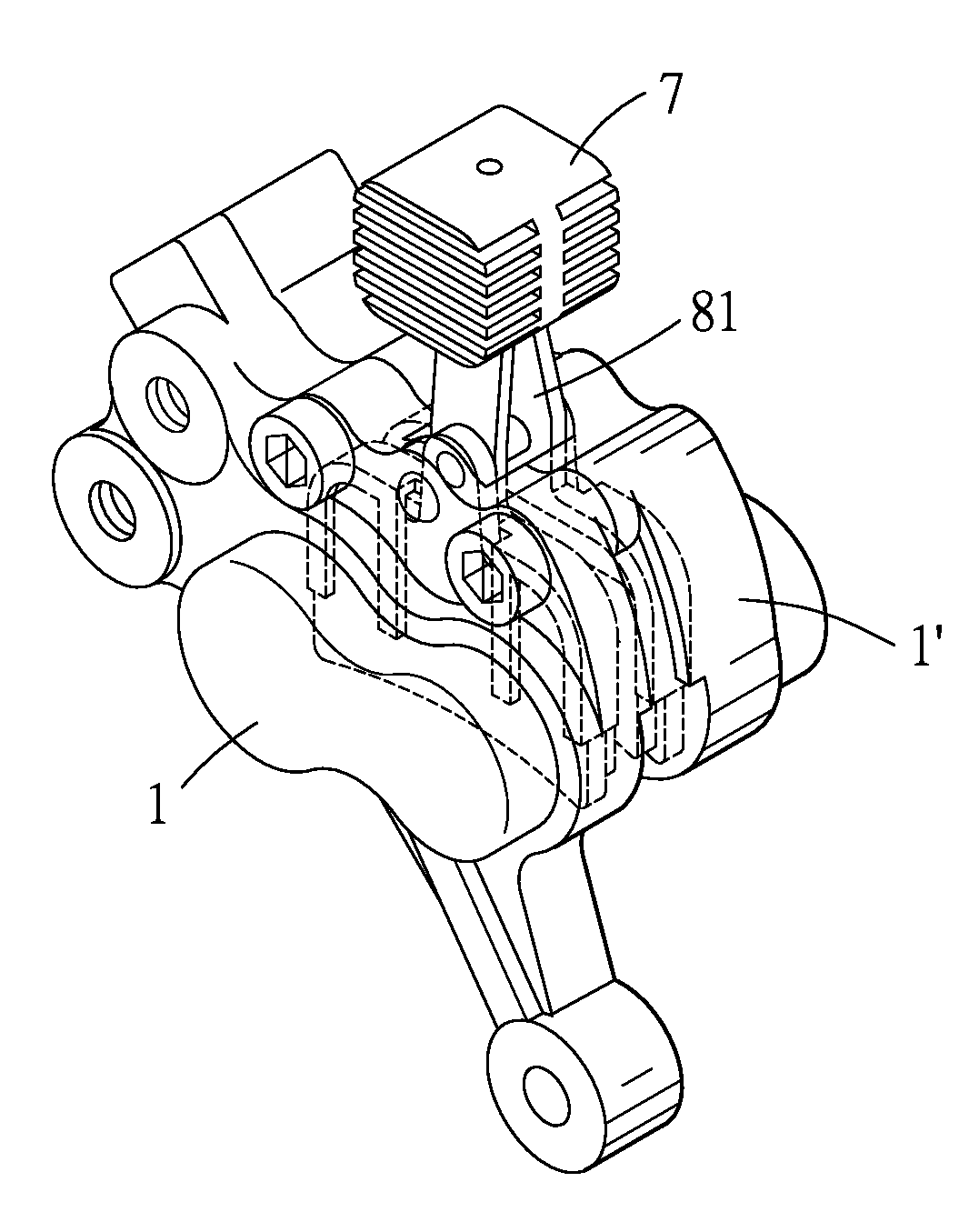
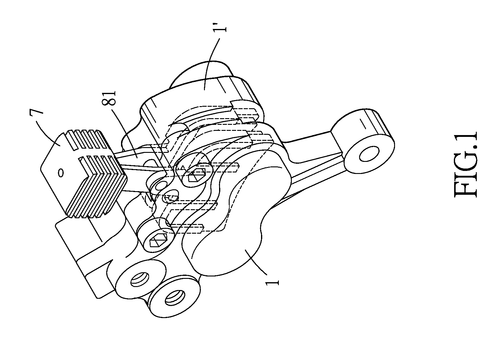
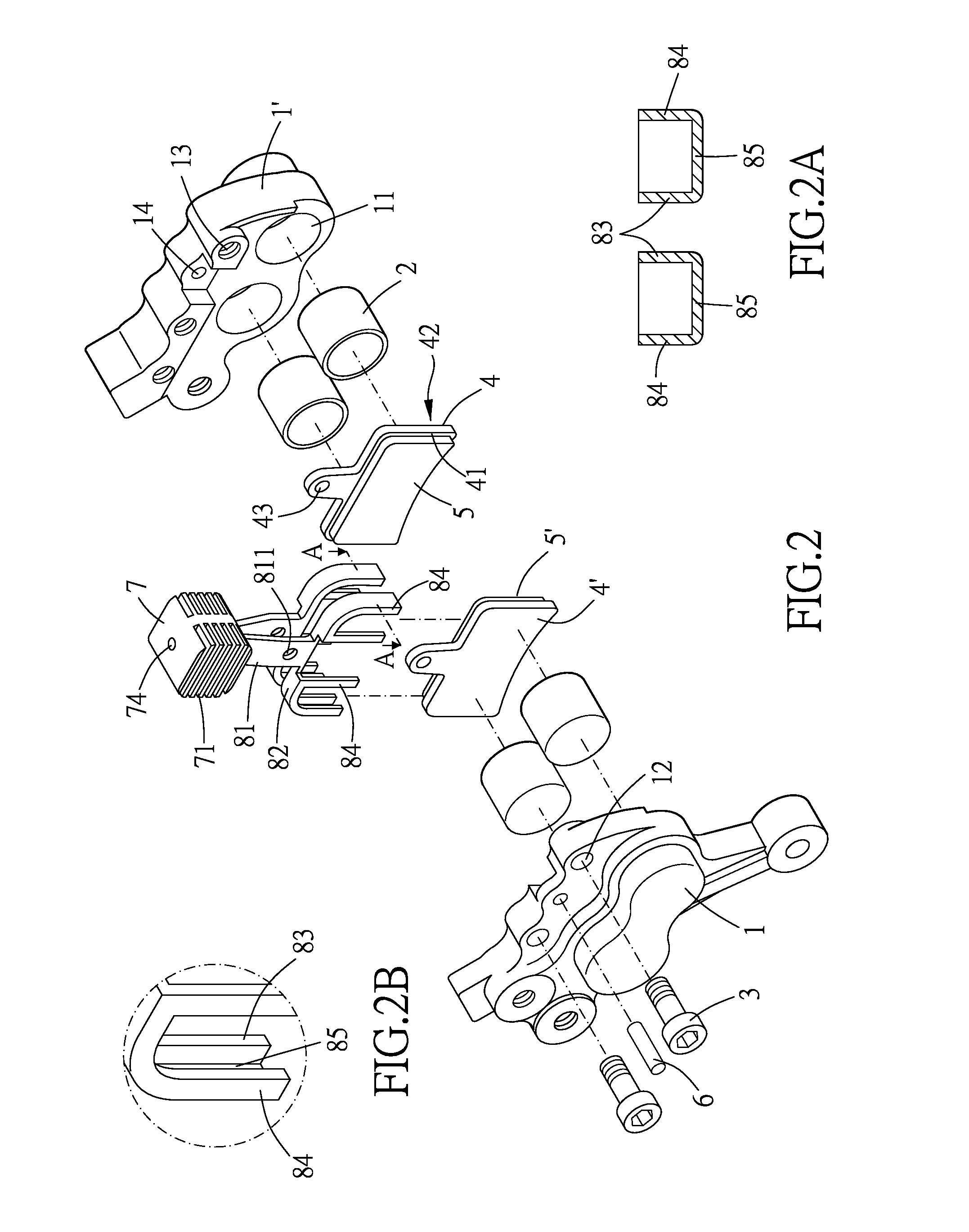
[0020]Please refer to FIG. 1 to FIG. 4. The present invention provides a heat dissipation plate which is used for being disposed in a bicycle disc brake, wherein the bicycle disc brake includes two cases 1, 1′, four pistons 2, two fixing members 3, two back panels 4, 4′, two brake linings 5, 5′ and a pin 6.

[0021]The cases 1, 1′ are respectively formed with two pressure cylinders 11. Each of the pistons 2 is slidably received in each pressure cylinder 11. Each of the cases 1, 1′ is formed with a channel (unshown) which communicates with the pressure cylinders 11, so that the pistons 2 can be controlled by a liquid pressure to approach or depart from each other in pair. One of the cases 1 is formed with two through holes 12, and the other case 1′ is formed with two threaded holes 13. The fixing members 3 are respectively penetrate through the through holes 12 and are screwed into the threaded holes 13, so that the cases 1, 1′ are fixed to each other. In other possible embodiments of t...


PUM


Abstract

The present invention provides a heat dissipation plate which includes a heat dissipator and two elastic plates. The heat dissipation plate is adapted to be disposed in a bicycle disc brake. The elastic plates are fixed to the heat dissipator, and the elastic plates are disposed in the bicycle disc brake so as to fix the back panels of the brake linings in the disc brake. Thereby, the elastic plates of the present invention can conduct the heat, which is generated when braking, to the heat dissipator, so that it can prevent the brake linings from overheating when braking. The overheated brake linings may make the disc brake fail to stop the bicycle; therefore, the present invention can enhance the safety of the bicycle disc brake.

Description

BACKGROUND OF THE INVENTION[0001]1. Field of the Invention[0002]The present invention relates to a heat dissipation device for a brake, and more particularly to a heat dissipation device for a bicycle disc brake.[0003]2. Description of the Prior Art[0004]A conventional bicycle disc brake, as shown in TW 1329086, drives its pistons by a liquid pressure so as to make its brake linings to rub against the brake disc, so that it can reduce the rotation speed of the bicycle wheel. However, the brake linings are often overheated after rubbing with the brake disc, so that the disc brake may fail to function.[0005]Consequently, some back panels of the brake linings are improved so as to dissipate the heat from the brake linings, as shown in TWM343085 and TWM365418. However, the surface area of the back panels is just a little larger than the surface area of the brake linings, so that the improved back panels cannot dissipate the heat efficiently. Moreover, the back panels abut against the pi...

Claims


Application Information

Patent Timeline
IPC IPC(8): F16D65/847F16D55/225
CPCF16D65/847F16D55/228F16D2121/04F16D2065/789F16D2055/0091
Inventor WEN, YUAN-HUNG
Owner WEN YUAN HUNG
Why Eureka
Try Eureka