Temperature controlled child seat

Inactive Publication Date: 2021-09-02
COOK GAYLON
View PDF0 Cites 0 Cited by
  • Summary
  • Abstract
  • Description
  • Claims
  • Application Information

AI Technical Summary

Benefits of technology

[0008]In some exemplary embodiments, the housing member includ

Problems solved by technology

However, during extreme temperatures this may be difficult, especially if the child is sedentary in a stroller or a car seat.
The ina

Method used


Image

  • Temperature controlled child seat

Examples


Example

[0014]The present disclosure relates to a temperature controlled child seat device (“the device”). The child seat may include a car seat or a stroller. The device ensures that the child is comfortable regardless of the weather by providing a temperature management system in the child seat. The device operates a two-stage temperature management system which provides temperature management by way of direct heating or cooling of a seat cushion and back rest, and by way of providing blown out heated or chilled air through a vent assembly integrated in the device. In effect, the device provides a two-stage heating or cooling operation.

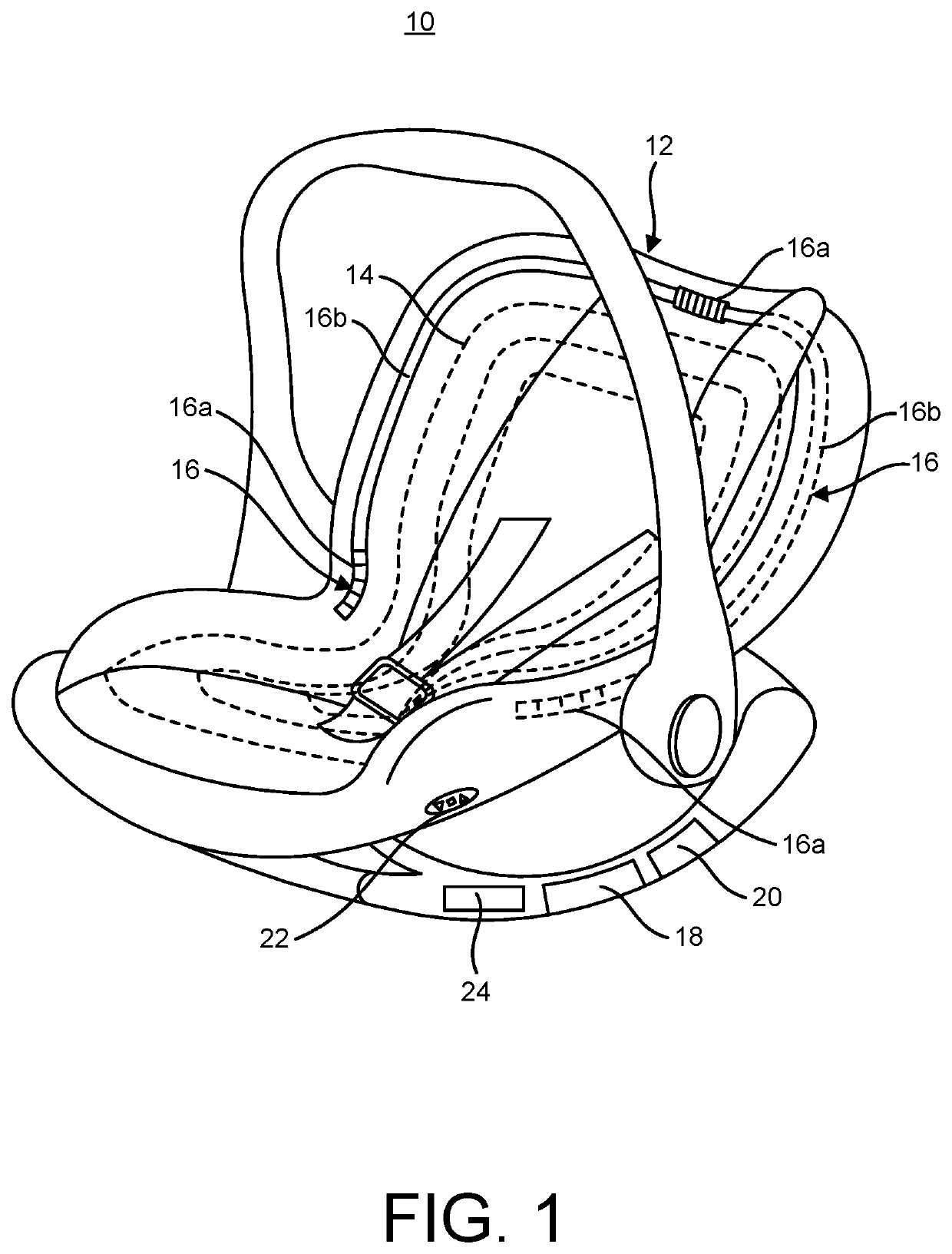
[0015]Turning to FIG. 1, the device 10 includes a housing member 12, a coil assembly 14, a vent assembly 16, a fan motor 18, a cooler / compressor 20, a temperature control member 22 and a battery compartment 24. The housing member 12 includes a seat cushion and back rest. The seat cushion receives a seat occupant. The back rest receives the occupant's back. ...


PUM


Abstract

A temperature controlled child seat device including a housing member, a coil assembly, a vent assembly, and a temperature control member. The housing member includes a seat cushion and a back rest. The coil assembly is embedded in the housing member and selectively produces heat and cooling in the seat cushion and back rest. The vent assembly is integrated in the housing member and includes a plurality of air openings and a vent line. The temperature control member initiates a two-stage heating or cooling operation in correspondence with a user selection of heating or cooling. The two-stage heating or cooling operation provides direct heating or cooling of the seat cushion and the back rest and provides heated or cooled air blown out of the vent assembly.

Description

FIELD OF THE INVENTION[0001]Embodiments described herein generally relate to child seats, and more particularly to a temperature controlled child seat.BACKGROUND OF THE INVENTION[0002]Ensuring that children are comfortable throughout various seasons is a major component of child care. However, during extreme temperatures this may be difficult, especially if the child is sedentary in a stroller or a car seat. The inability to manage temperature within these devices may cause discomfort for the child, and in extreme temperatures it may cause death. Hence, it is desirable to develop a means to manage the temperature of a child's stroller or a car seat.BRIEF DESCRIPTION OF THE DRAWINGS[0003]The various advantages of the embodiments of the present disclosure will become apparent to one skilled in the art by reading the following specification and appended claims, and by referencing the following drawing(s), in which:[0004]FIG. 1 shows an exemplary front view of a temperature controlled c...

Claims


Application Information

Patent Timeline
IPC IPC(8): B60N2/56B60N2/26
CPCB60N2/5621B60N2/5685B62B9/00B60N2/5692B60N2/26B60N2/5614B60N2/5657B62B2204/04B62B2204/02B62B2204/00B62B9/102
Inventor COOK, GAYLON
Owner COOK GAYLON
Why Eureka
Try Eureka