Object detection for a power transfer system

Active Publication Date: 2015-12-03
ROBERT BOSCH GMBH
View PDF0 Cites 0 Cited by
  • Summary
  • Abstract
  • Description
  • Claims
  • Application Information

AI Technical Summary

Benefits of technology

[0017]The method may be implementable in a conventional inductive power transfer system. If an object was determined, the power transfer may be throttled or stopped in order to prevent overheating of the object and to reduce an accident risk associated with that.
[001

Problems solved by technology

If the object is magnetizable, the object may also be heated through core or hysteresis losses.
The heating may be considerable, so that an operational reliability of the transmitter or of the receiver cannot be ensured.
Moreover, the object may withd

Method used


Image

  • Object detection for a power transfer system
  • Object detection for a power transfer system
  • Object detection for a power transfer system

Examples


Embodiment Construction

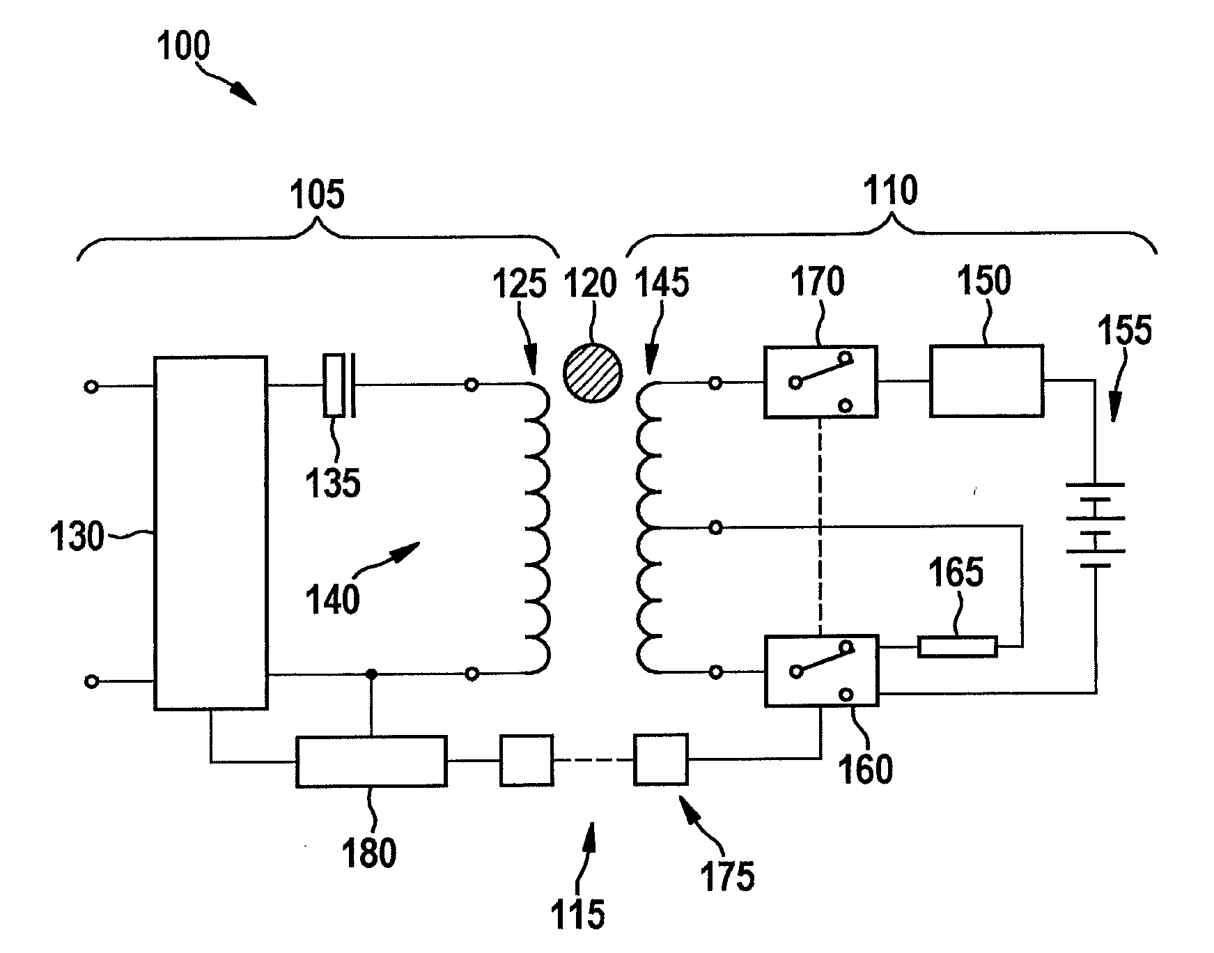
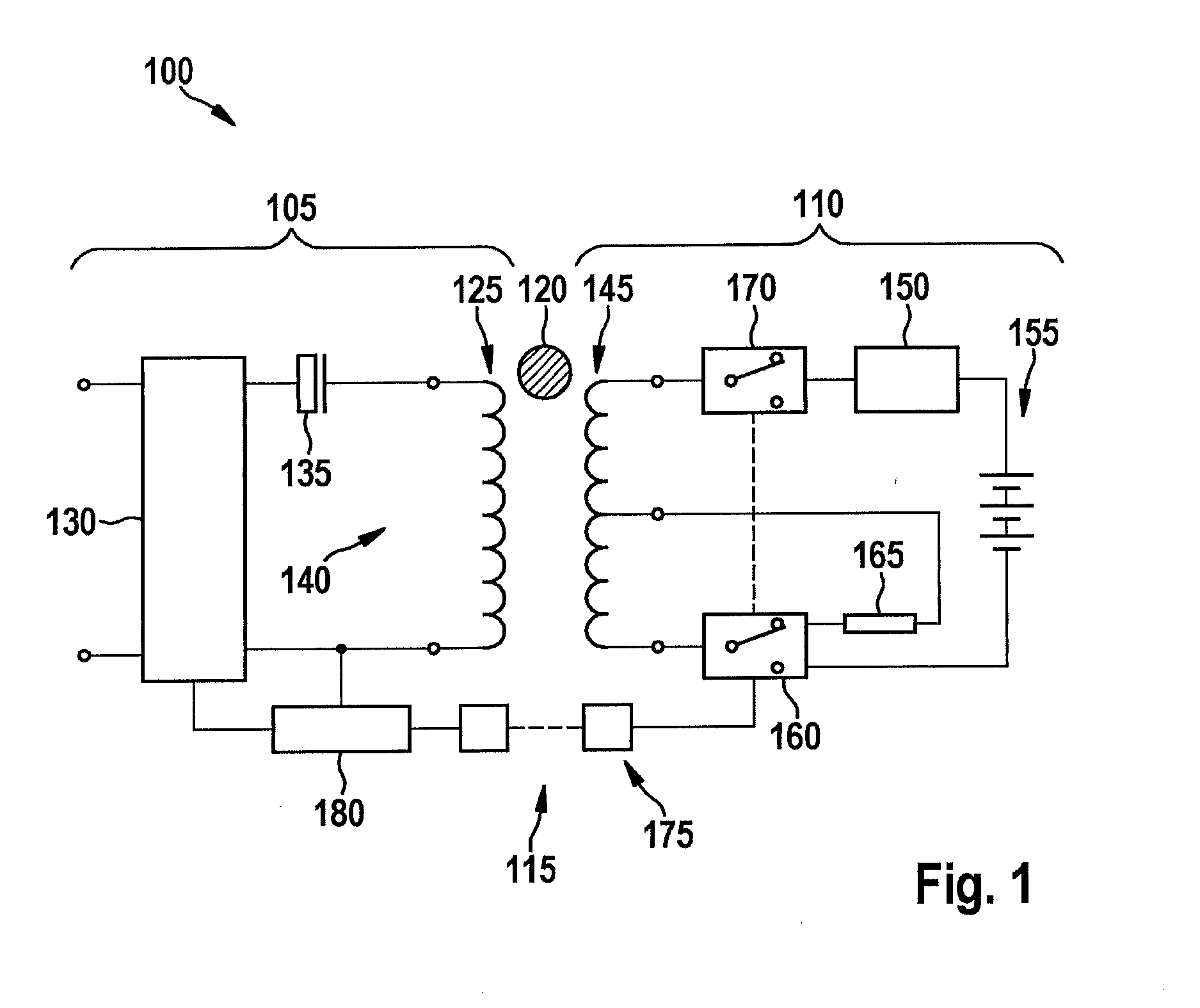
[0027]FIG. 1 shows a system 100 for wireless power transfer. System 100 includes a transmitting device 105 and a receiving device 110 between which a power transfer path 115 is defined. In the area of power transfer path 115, an object 120 may be present. Object 120 is conductive or magnetizable, so that a changing magnetic field could cause eddy currents, hysteresis losses, or core losses in object 120 which heat object 120. It is the object of illustrated system 100 to determine the existence of object 120.

[0028]Transmitting device 105, which may be included in a power supply, for example, includes a transmitting coil 125 for converting an electric current in a magnetic field in the area of power transfer path 115. Transmitting coil 125 is connected to a voltage source 130 which makes available an alternating current. Voltage source 130 may be connected to a conventional power supply system. A resonance capacitor 135 is preferably connected to transmitting coil 125 in series with ...


PUM


Abstract

A power transfer system includes: a transmitting device having a transmitting coil and a receiving device having a receiving coil, the two coils being inductively coupleable to one another for the purpose of transferring power, so that a power transfer path exists between them; an electrical load for connecting with terminals of the receiving coil; a detection device for detecting an electrical parameter which indicates the inductance of the transmitting coil while the electrical load is connected to the receiving coil; and a determination device for determining an object in the area of the power transfer path on the basis of the detected parameter.

Description

BACKGROUND OF THE INVENTION[0001]1. Field of the Invention[0002]The present invention generally relates to a wireless power transfer, and the present invention particularly relates to a system and a method for detecting an object on a power transfer path of a wireless power transfer.[0003]2. Background of the Invention[0004]A small power device includes a consumer and an accumulator in order to allow for wireless utilization. To charge the accumulator, power may be transferred wirelessly from a power supply to the small device by using an electromagnetic field to transfer power. For this purpose, the power supply and the small device each include a coil, the coils being positioned at a small distance from one another and thus essentially together forming a transformer.[0005]If an electrically conductive object gets into the area of the electromagnetic field, eddy currents may form which heat the object. If the object is magnetizable, the object may also be heated through core or hys...

Claims


Application Information

Patent Timeline
IPC IPC(8): G01V3/38H02J5/00G01V3/10
CPCG01V3/38H02J5/005G01V3/101H02J7/025H02J50/12H02J50/60H02J50/70
Inventor MACK, JUERGEN
Owner ROBERT BOSCH GMBH
Why Eureka
Try Eureka