Furnace apparatus

Active Publication Date: 2016-12-13
SERENDIPITY TECH LLC
View PDF0 Cites 9 Cited by
  • Summary
  • Abstract
  • Description
  • Claims
  • Application Information

AI Technical Summary

Benefits of technology

[0007]In an embodiment, the furnace apparatus further comprises a bottom stirrer positioned at a lower section of the lower combustion section, where the bottom stirrer is configured to stir the solid waste during the combustion process. In an embodiment, the furnace apparatus further comprises a bottom airlock positioned below the lower combustion section, where the bottom airlock is configured to prevent expulsion of combusted air through a lower section of the lower combustion section. In an embodiment, the furnace apparatus fur

Problems solved by technology

Solid waste disposal has been a major issue in many countries, especially in the USA where there is a need for elimination of landfill problems for garbage disposal.
But eventually, climatic changes like rainfall and change in the level of water table discouraged this practice in the long run.
One of the important disadvantages to the incineration process is that numerous stable and toxic compounds, comprising polychlorinated dibenzodioxins or “dioxins” and polychlorinated bidenzofurans, are formed and are present

Method used


Image

  • Furnace apparatus
  • Furnace apparatus
  • Furnace apparatus

Examples


Example

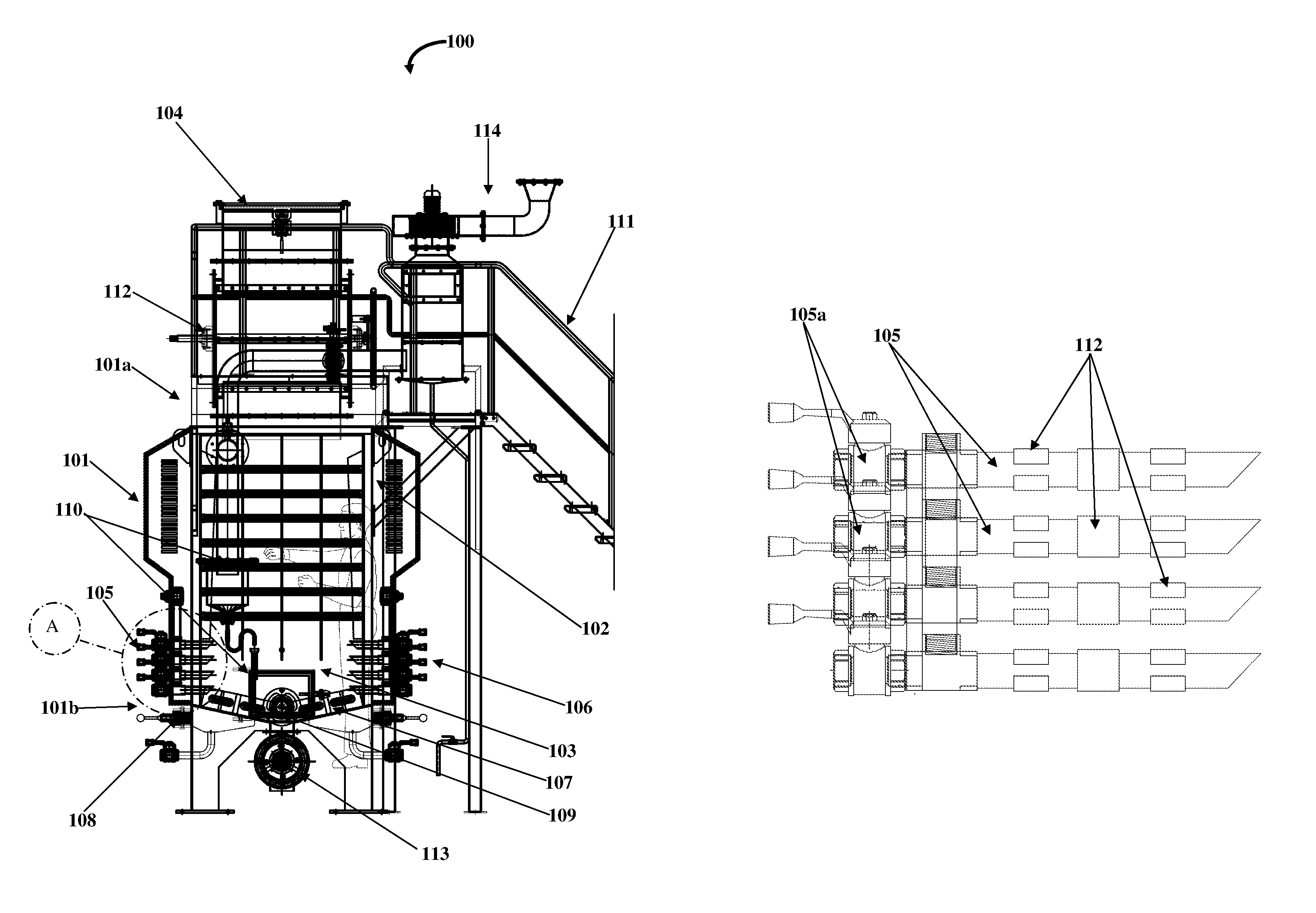
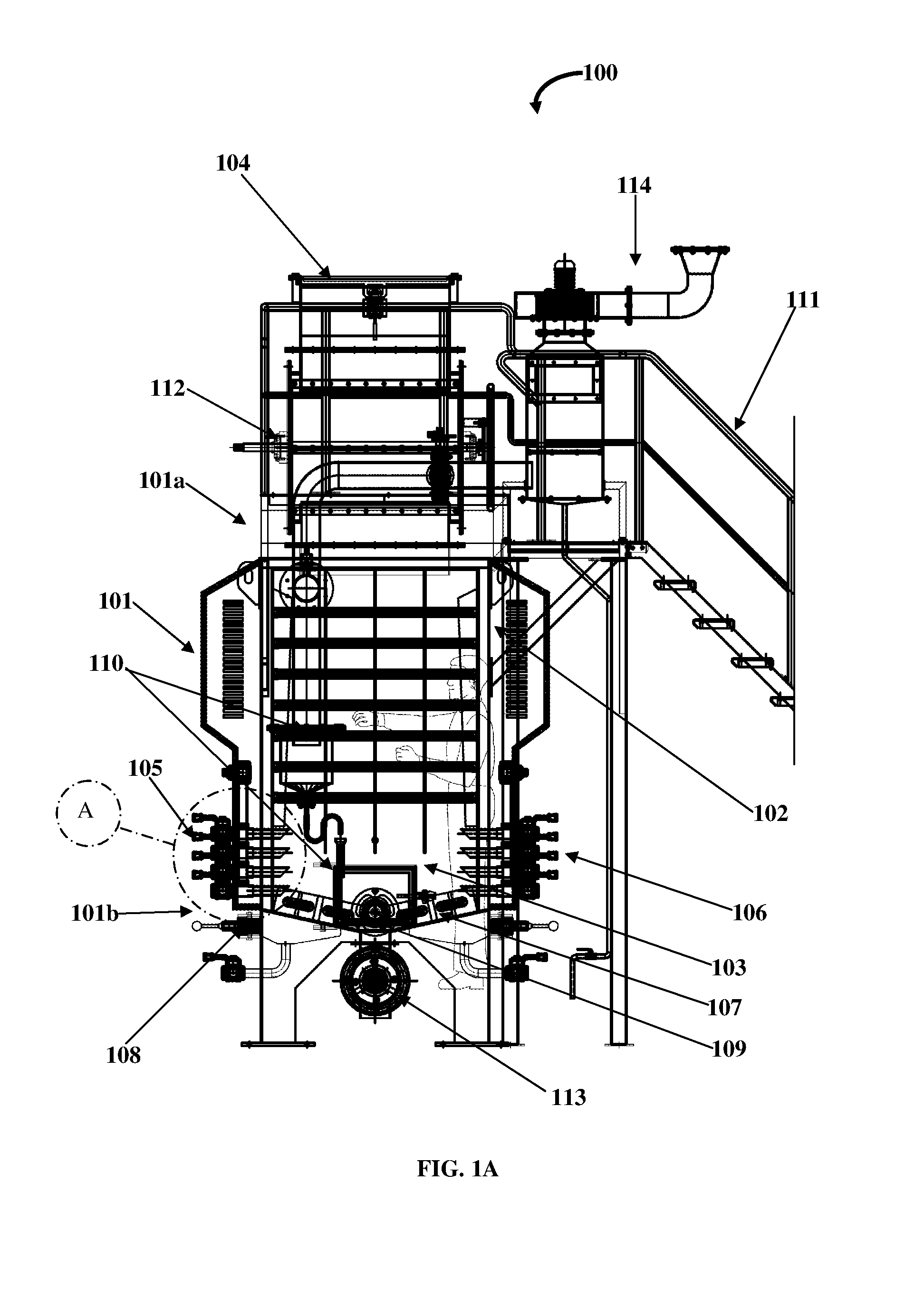
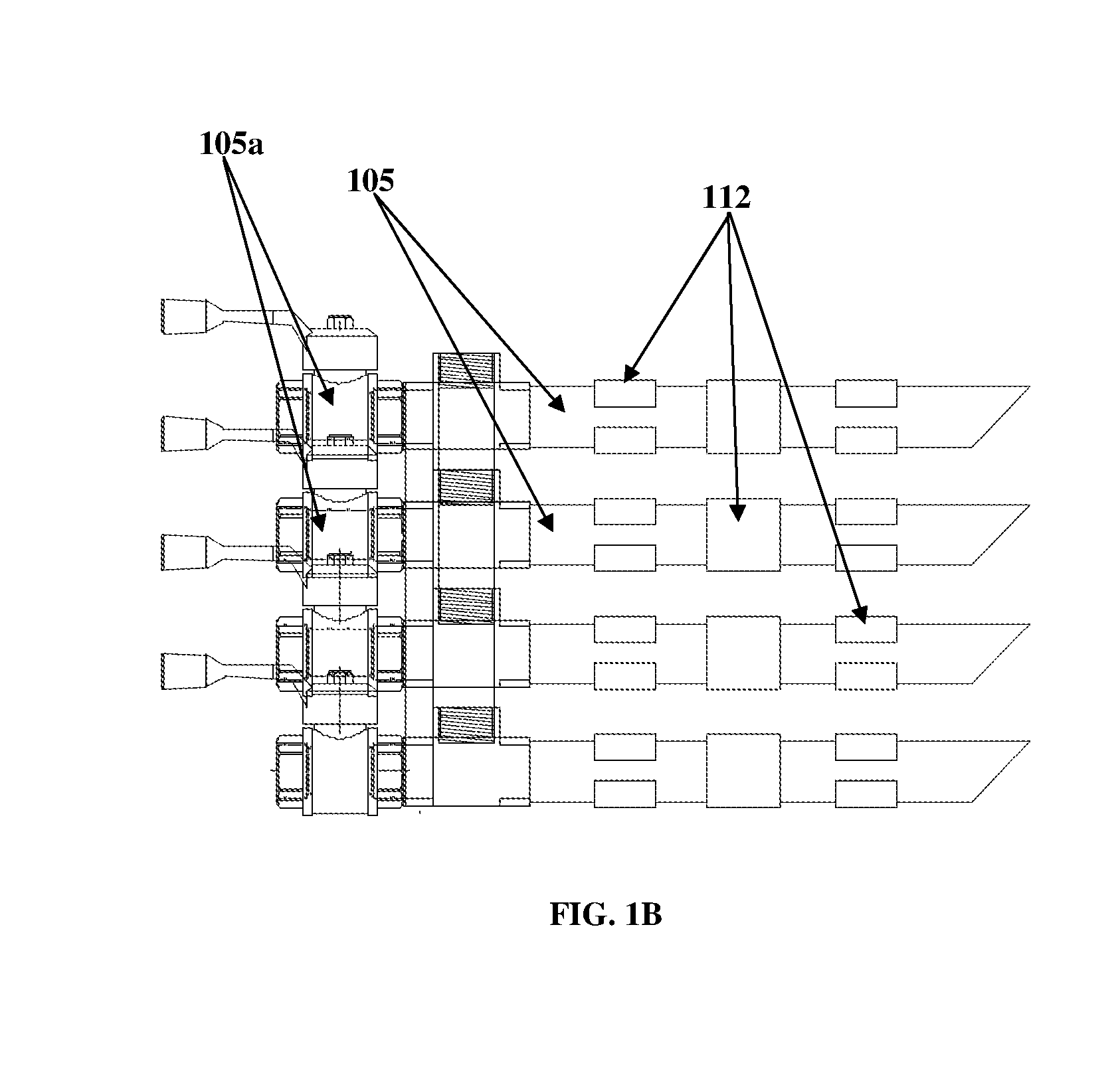
[0018]FIG. 1A exemplarily illustrates is a front perspective of the furnace apparatus 100, FIG. 1B exemplarily illustrates is an enlarged view of the portion marked A in FIG. 1A which shows a perspective view of the air inlet pipe 105 with magnets 112 positioned on the surface, FIG. 1C exemplarily illustrates is an enlarged view of the portion marked A in FIG. 1A which shows a perspective view of one of the air outlet pipe 106 and the air inlet pipe 105 with magnets 112 positioned on the surface, and FIG. 1D exemplarily illustrates is an enlarged view of the portion marked A in FIG. 1A which shows a perspective view of an embodiment of one of the air outlet pipe 106 and the air inlet pipe 105 with six magnets 112 positioned on the surface. The term “magnets” will be, herein after referred to as “Neodymium iron boron blocks”. The furnace apparatus 100 disclosed herein is configured to incinerate solid waste, and comprises a generally chamber 101, a solid waste feed inlet 104, multipl...


PUM


Abstract

A furnace apparatus to incinerate solid waste comprises a chamber, a solid waste feed inlet, air inlet pipes, and air outlet pipes. The chamber includes an upper pyrolysis section and a lower combustion section, and the solid waste feed inlet is positioned at an upper portion of the chamber to feed solid waste to the lower combustion section. The air inlet pipes receive air for combustion of the solid waste within the lower combustion section. The air outlet pipes exhaust combusted air from the lower combustion section, where multiple magnets are operably attached on the air inlet pipes and the air outlet pipes. The paramagnetic oxygen present in the received air is concentrated via the magnets, and the concentrated oxygen is introduced into a plasma generated within the combustion section to accelerate the combustion process, and to oxidize toxic matter present in the solid waste.

Description

BACKGROUND[0001]Solid waste disposal has been a major issue in many countries, especially in the USA where there is a need for elimination of landfill problems for garbage disposal. Traditionally, in the past, most of the solid waste was burned and was disposed off under the soil. But eventually, climatic changes like rainfall and change in the level of water table discouraged this practice in the long run. So there was a need for a more compact and strategic method to dispose solid waste. Therefore incinerators were invented which specialized in the burning and disposal of solid waste in disposable form according to safety and pollution standards around the world.[0002]Incineration process is striking substitute for dumping for the disposal of garbage, and is performed throughout the world and results in a substantial reduction in the volume of solid waste and the retrieval of energy, for example, as electricity or steam. One of the important disadvantages to the incineration proce...

Claims


Application Information

Patent Timeline
IPC IPC(8): F23G5/00F23G5/44F23G5/32
CPCF23G5/442F23G5/32F23G5/085F23G5/14F23G5/24F23G5/444F23G2204/201F23G2205/18F23L2900/00001Y02E20/34Y02P80/15F23G5/027F23L7/007F23G2201/30
Inventor DHYLLON, AMEN
Owner SERENDIPITY TECH LLC
Why Eureka
Try Eureka