Secondary Part of a Synchronous Motor Having a Protective Device for Magnets

Active Publication Date: 2015-12-17
ETEL SA
View PDF6 Cites 3 Cited by
  • Summary
  • Abstract
  • Description
  • Claims
  • Application Information

AI Technical Summary

Benefits of technology

[0008]Example embodiments of the present invention simplify and inexpensively im

Problems solved by technology

The magnets can corrode, for example, if they come in contact with liquids.
In addition, they are susceptible to mechanical damage.
This is a problem primarily in machine tools,

Method used


Image

  • Secondary Part of a Synchronous Motor Having a Protective Device for Magnets
  • Secondary Part of a Synchronous Motor Having a Protective Device for Magnets
  • Secondary Part of a Synchronous Motor Having a Protective Device for Magnets

Examples


Embodiment Construction

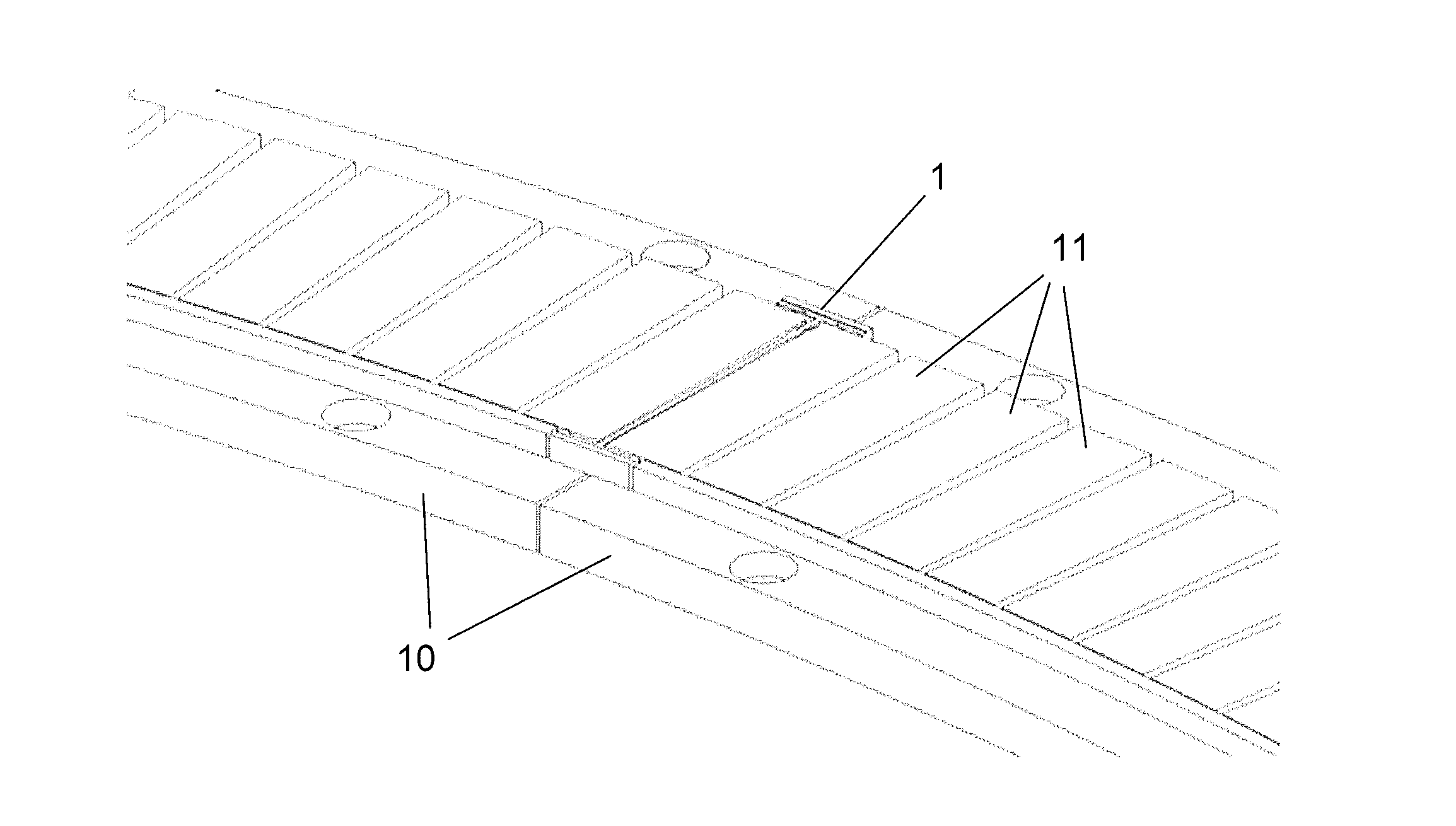
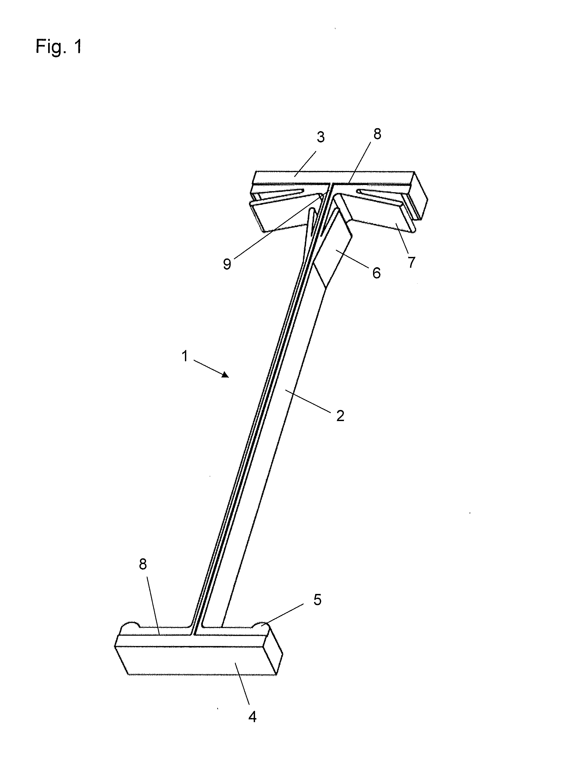
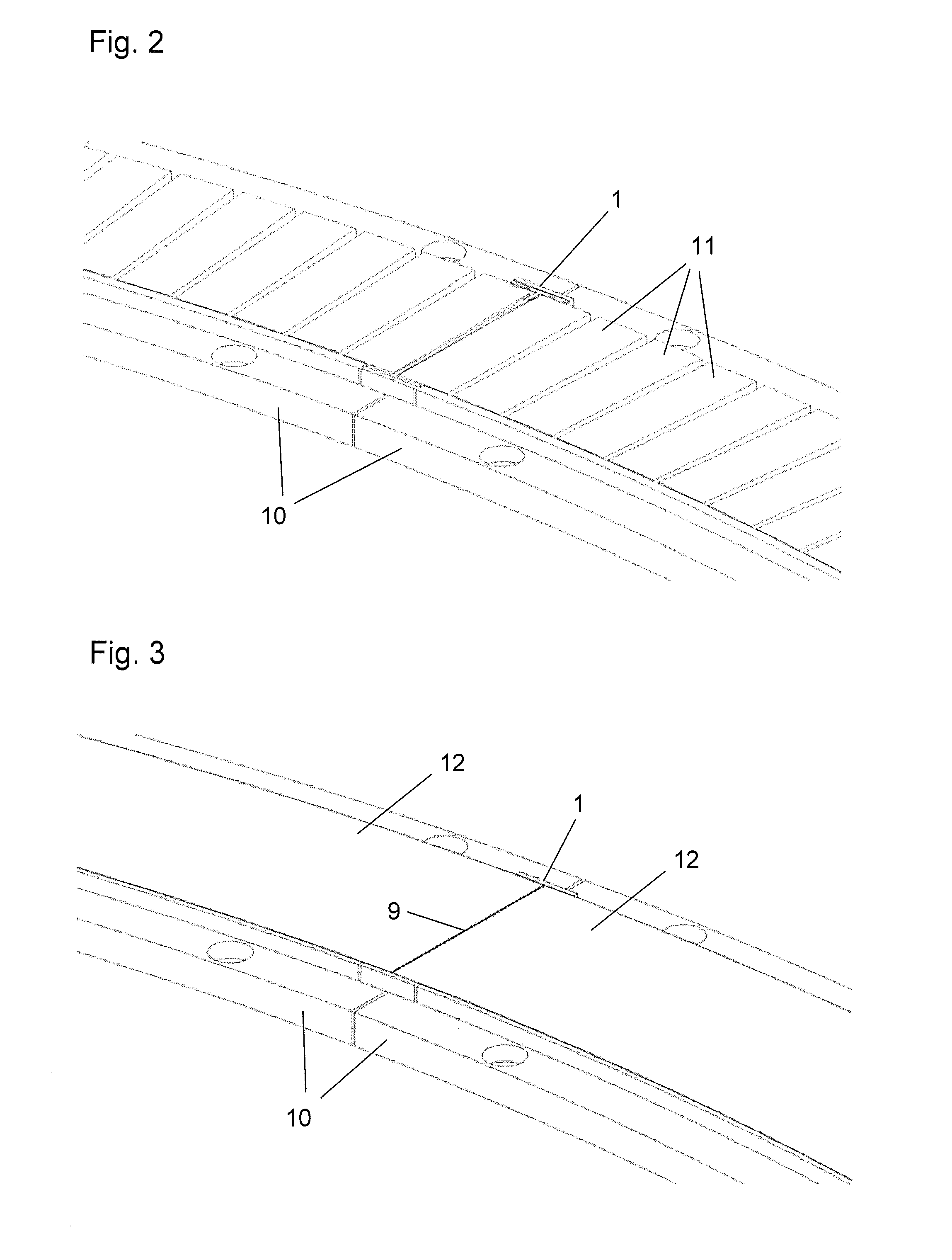
[0017]FIG. 1 is a perspective view of a protective device 1 for the magnetic path of a synchronous motor. FIG. 2 illustrates the protective device 1 in a typical mounting situation in a linear motor. The protective device in the form of a double-T structure, which may be produced as an injection-molded part, is inserted between magnets 11 that are disposed on a magnet support 10 and form the magnetic path of the linear motor.

[0018]Protective device 1 includes a web 2 that is inserted into the gap between two magnets 11. Arranged at the two ends of web 2 are two flanges 3, 4 projecting at right angles on both sides of web 2. These flanges rest against the outer edges of magnets 11 exposed on both sides of the magnetic path.

[0019]Integrally molded on web 2 are first spring elements 6, which are arranged to center web 2 in the gap between two magnets 11. In this manner, protective device 1 may be used in magnetic paths whose magnets 11 have different spacings, where the gap between two...


PUM


Abstract

A secondary part of a synchronous motor has a protective device for magnets. The secondary part has a plurality of magnets evenly spaced on a magnet support. The protective device has a web for insertion into the gap between adjacent magnets. The web has a first and second flange at its two ends, so that the web and the flanges form a double-T structure, and the flanges rest against outer edges of the adjacent magnets.

Description

CROSS-REFERENCE TO RELATED APPLICATIONS[0001]The present application claims priority to Application No. 14171949.2, filed in the European Patent Office on Jun. 11, 2014, which is expressly incorporated herein in its entirety by reference thereto.FIELD OF THE INVENTION[0002]The present invention relates to a secondary part of a synchronous motor, having a protective device for magnets. Such protective devices are used to protect the magnets of the magnetic path of a synchronous motor from damage due to external influences.BACKGROUND INFORMATION[0003]Synchronous motors, which include a primary part having coils and a secondary part having permanent magnets, have been known for a long time. For example, U.S. Pat. No. 5,642,013 describes synchronous motors in which magnets are placed in evenly spaced fashion and with alternating polarity on a magnetic path. Opposite this magnetic path is a primary part, on whose teeth coils are wound. In response to suitable energizing of the coils, a f...

Claims


Application Information

Patent Timeline
IPC IPC(8): H02K5/10
CPCH02K5/10H02K41/031H02K1/17H02K2201/03
Inventor FERNANDES GONCALVES, JOSE MANUELGRILLON, JEAN-YVES
Owner ETEL SA
Why Eureka
Try Eureka