Electric candle with illuminating panel

a technology of electric candles and illumination panels, applied in the field of electric candles with illumination panels, can solve problems such as fire risk, surface damage, and hazards

Inactive Publication Date: 2015-12-24
L&L CANDLE CO LLC
View PDF0 Cites 40 Cited by
  • Summary
  • Abstract
  • Description
  • Claims
  • Application Information

AI Technical Summary

Benefits of technology

[0006]The following presents a simplified summary of one or more embodiments of the present disclosure in order to provide a basic understanding of such embodiments. This summary is not

Problems solved by technology

Traditional candles however, provide a variety of hazards including risk of fire, damage to surfaces caused by hot wax, and the possible emission of soot.
How

Method used


Image

  • Electric candle with illuminating panel
  • Electric candle with illuminating panel
  • Electric candle with illuminating panel

Examples


Embodiment Construction

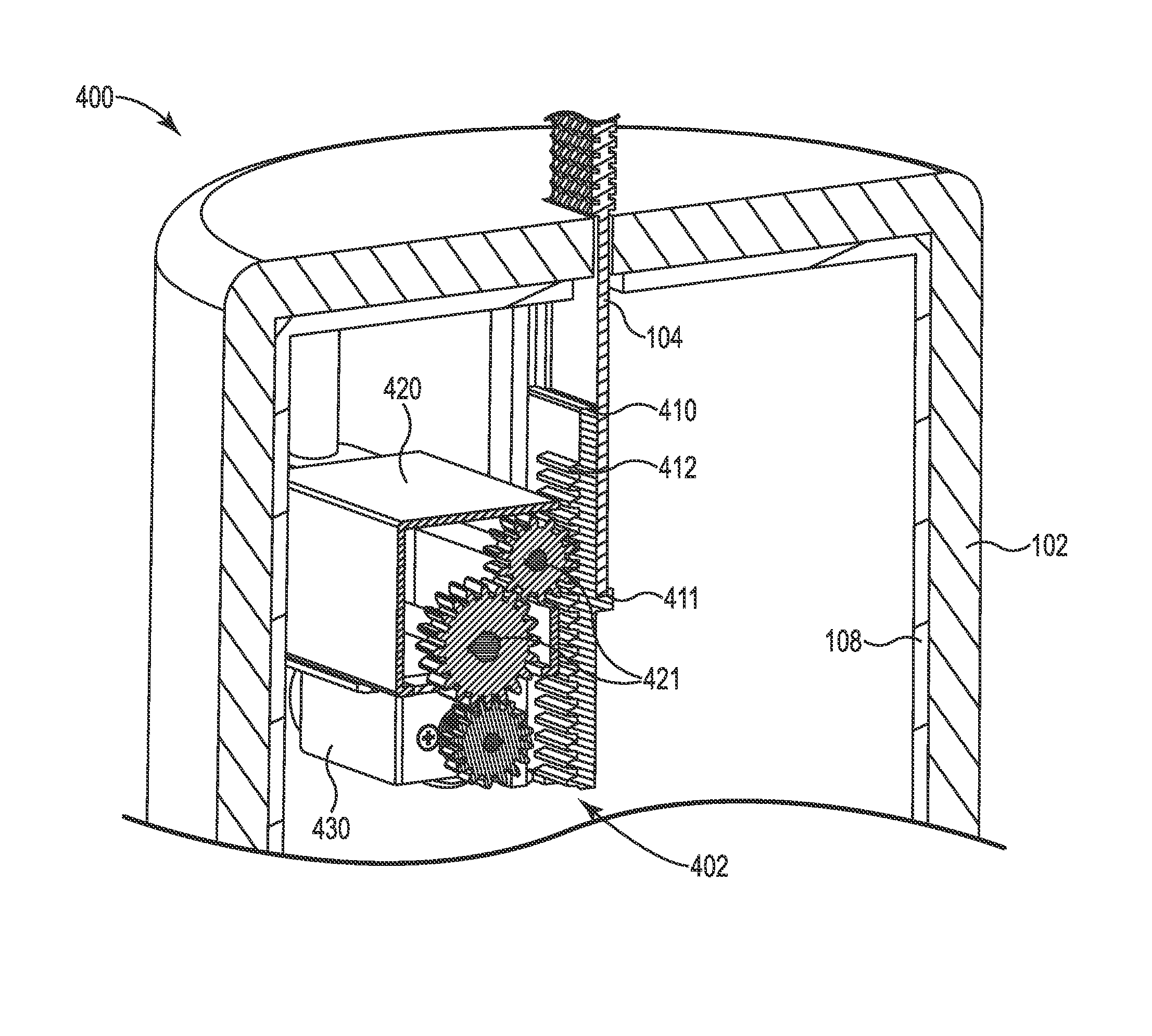
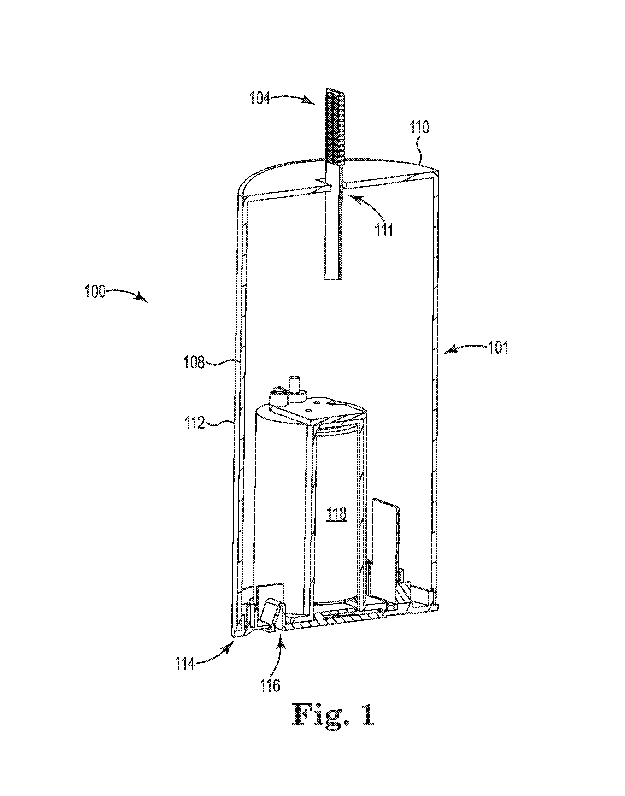
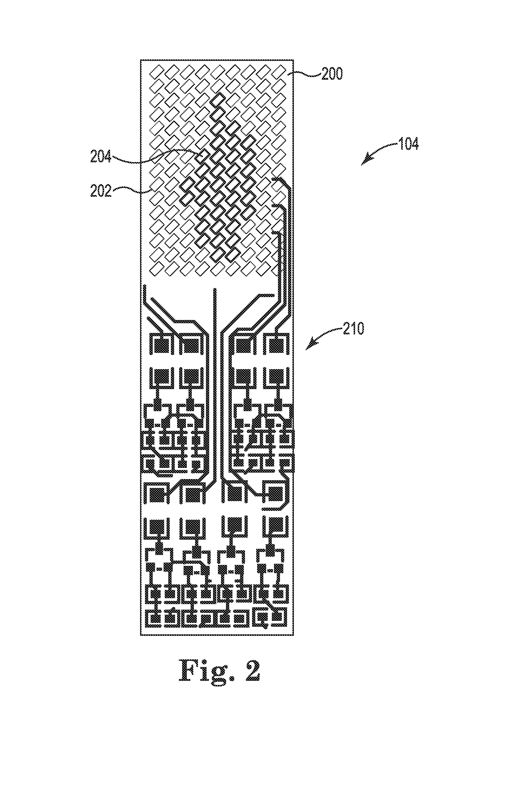
[0034]The present disclosure relates to novel and advantageous flameless candles. Particularly, the present disclosure relates to novel and advantageous flameless candles simulating a realistic flame on a LED panel or matrix.

[0035]The present disclosure relates to a flameless candle and flameless light that uses a LED light source to provide the appearance of a natural flame and flame-like flicker of light. The flameless candle may include a body having a top surface, a bottom surface upon which the body rests, and a sidewall between the bottom surface and the top surface. In another embodiment, the flameless candle may include a body having a bulb like cover and a mounting base or end cap, which may, in some embodiments, connect to a traditional light socket. One or more control switches may be used to provide a variety of functions when activated separately or together, including but not limited to, turning the light source ON or OFF, operating the light source in a static or dyna...


PUM


Abstract

The present disclosure, in one embodiment, relates to an electric flameless candle, comprising a body configured in shape and size to simulate a true flame candle. The electric flameless candle further comprising a light source operably connected to the body and positioned to be generally protruding from an exterior surface of the body, the light source comprising a plurality of illuminators electrically operated to illuminate in a way that simulates the movement of a real candle's flame.

Description

CROSS-REFERENCE TO RELATED APPLICATIONS[0001]This application claims the benefit of Chinese Patent Application No. 201420342430, filed on Jun. 24, 2014, entitled “A Simulated Flame Lighting Device,” is a continuation-in-part of U.S. patent application Ser. No. 14 / 449,865, filed on Aug. 1, 2014, entitled “Electronic Candle with Illuminating Panel,” and is a continuation-in-part of PCT / CN2014 / 087931, filed Sep. 30, 2014, the disclosures of which are hereby incorporated by reference herein in their entirety.FIELD OF THE INVENTION[0002]The present disclosure relates to novel and advantageous flameless electric candles. Particularly, the present disclosure relates to electric candles simulating a realistic flame of a true flame candle.BACKGROUND OF THE INVENTION[0003]The background description provided herein is for the purpose of generally presenting the context of the disclosure. Work of the presently named inventors, to the extent it is described in this background section, as well as...

Claims


Application Information

Patent Timeline
IPC IPC(8): F21S6/00F21V23/00F21S10/04H05B44/00
CPCF21S6/001F21S10/046F21Y2105/001F21V23/003F21S10/043F21S9/02F21V3/02F21W2121/00F21Y2105/10F21K9/232F21Y2115/10F21K9/238F21Y2101/00F21K9/23H05B45/10F21V23/04
Inventor LI, XIAOFENG
Owner L&L CANDLE CO LLC
Why Eureka
Try Eureka