
Flameless candle with threaded insert and method for assembling the same

a technology of threaded inserts and flameless candles, which is applied in the direction of lighting, decorative arts, and combustion process protection devices, can solve the problems of affecting the effect of flameless candles

Inactive Publication Date: 2012-12-25
WINVIC SALES
View PDF10 Cites 3 Cited by
  • Summary
  • Abstract
  • Description
  • Claims
  • Application Information

AI Technical Summary

Benefits of technology

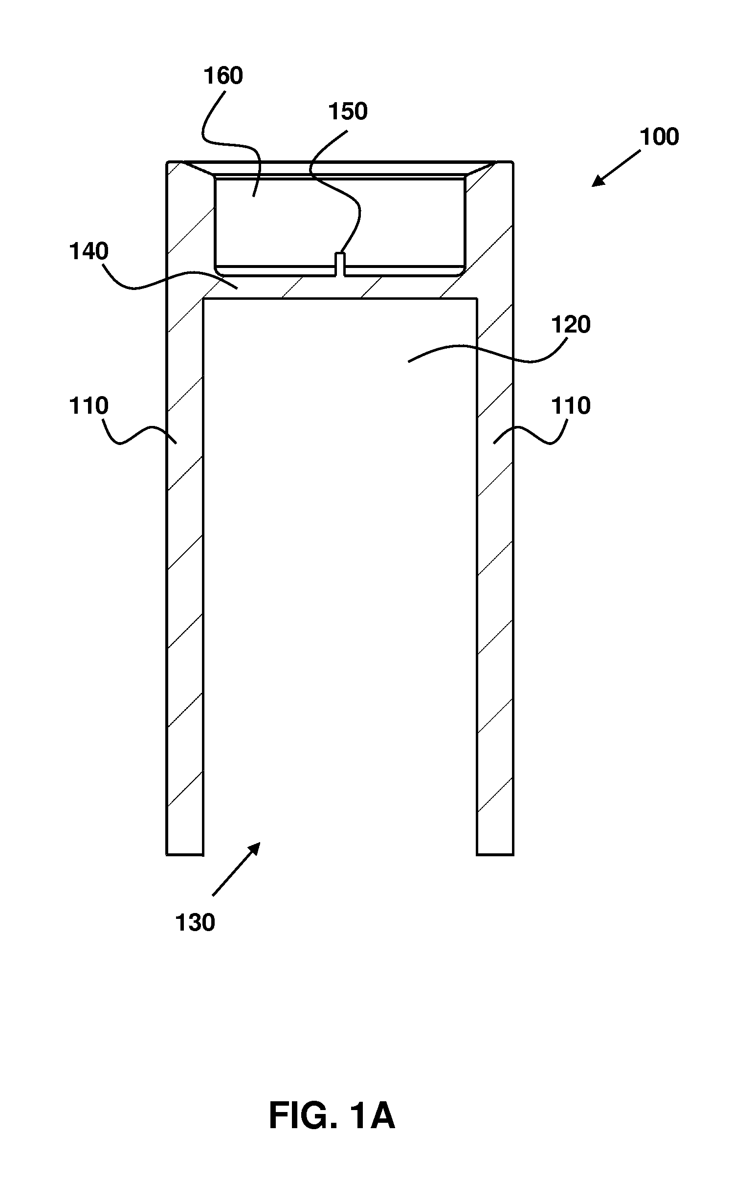
[0011]This flameless candle also has an electronics insert. The insert has a housing. At least one thread (for example, an exterior thread or male thread) is arranged on a lateral portion of the housing. This thread (or threads as used herein) can be rotated in response to a torque force on the electronics insert. The rotation causes the electronics insert to be drawn through the opening and into the hollow region, thereby substantially securing the electronics insert to the candle shell.
[0015]The rotation of the electronics insert and the threads may be facilitated through the use of a tool. The tool may be inserted into the battery compartment of the electronics insert. The electronics insert may be rotated while the waxen sidewall is still, or vice versa.

Problems solved by technology

While the waxen material may provide such benefits, it can be relatively expensive.
This process, however, can be relatively expensive and time consuming during the manufacturing process.
Additionally, the steps of adding the sealant and waiting for drying take time.
Moreover, the electronics insert may be damaged by the sealant (for example, hot wax) and, therefore, it may be useful to perform an additional step of protecting the insert before the sealant is applied.
These techniques may also require a relatively complex production flow and expensive machine costs.

Method used


Image

  • Flameless candle with threaded insert and method for assembling the same
  • Flameless candle with threaded insert and method for assembling the same
  • Flameless candle with threaded insert and method for assembling the same

Examples


Embodiment Construction

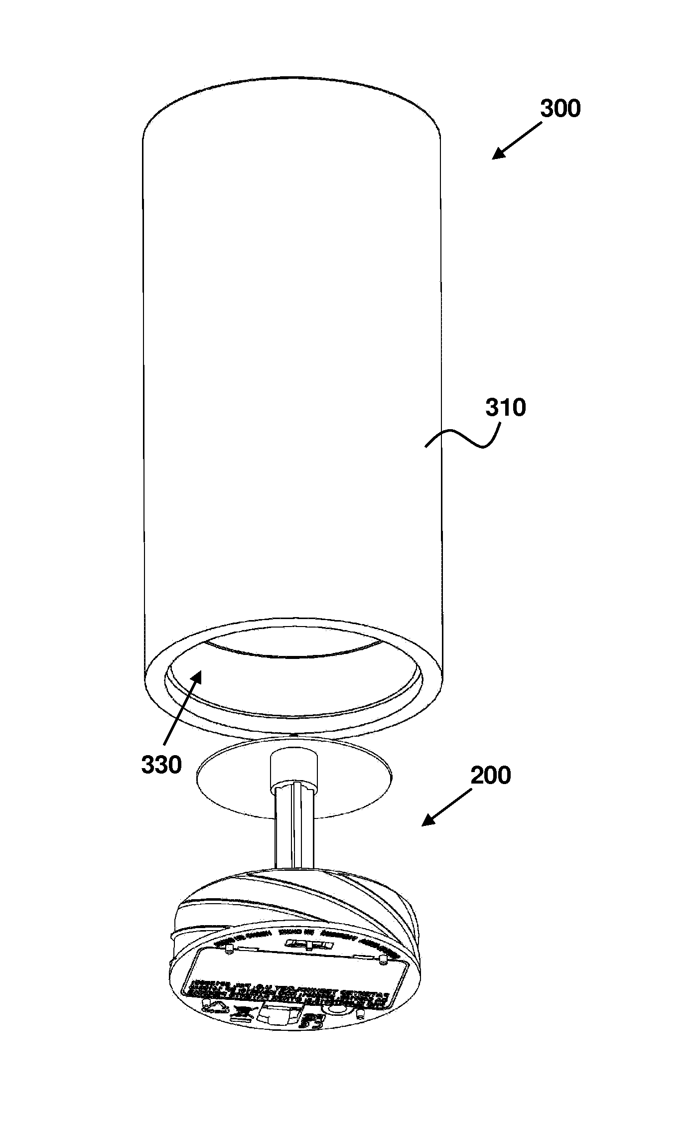
[0028]FIGS. 2A and 2B show views of an electronics insert 200, according to an embodiment of the present invention. The electronics insert may include a light-emitting diode (“LED”) 210, a light diffusing member 220, a lateral portion 230 of a housing, one or more threads 240, and a battery compartment 250.

[0029]The LED 210 may produce a flickering light when turned on. The light diffusing member 220 may diffuse the light emitted by the LED 210 to promote the illusion of a traditional candle. The battery compartment 250 may be opened from the bottom of the electronics insert 200, for example, with a spring-latched door. The battery compartment 250 may hold the batteries that provide power to the LED 210. The electronics insert 200 may also include a base 260. As shown, the exterior of the lateral portion 230 is tapered (that is, it is shown having an angle that is not perpendicular to the base 260), although other orientations are possible—for example, non-tapered.

[0030]One or more ...


PUM

PropertyMeasurementUnit
torque forceaaaaaaaaaa
insertion depthaaaaaaaaaa
rotationaaaaaaaaaa

Abstract

According to embodiments of the present invention, a flameless candle is claimed, depicted, and described. The candle has a candle shell, which includes a sidewall (such as a waxen sidewall) surrounding a hollow region. There is an opening through the bottom of the candle shell leading into the hollow region. This flameless candle also has an electronics insert. The insert has a housing. At least one thread (for example, an exterior thread or male thread) is arranged on a lateral portion of the housing. This thread (or threads as used herein) can be rotated in response to a torque force on the electronics insert. The rotation causes the electronics insert to be drawn through the opening and into the hollow region, thereby substantially securing the electronics insert to the candle shell.

Description

RELATED APPLICATIONS[0001][Not Applicable]FEDERALLY SPONSORED RESEARCH OR DEVELOPMENT[0002][Not Applicable]MICROFICHE / COPYRIGHT REFERENCE[0003][Not Applicable]BACKGROUND OF THE INVENTION[0004]Generally, the present application relates to flameless candles. Particularly, the present application relates to techniques for screwing an electronics insert into a waxen sidewall of a candle shell.[0005]Flameless candle designs may use candle shells that include wax or a waxen material. As used herein, a waxen material is encompassing of wax, a wax substitute, or similar materials. The waxen material may allow the flameless candle to appear more like a traditional candle. While the waxen material may provide such benefits, it can be relatively expensive.[0006]Because a flameless candle does not typically consume the candle, it may not be necessary to have a candle body that is completely solid. Instead, it may be preferable to have a hollow region within the candle body, such as a candle she...

Claims


Application Information

Patent Timeline
Patent Type & Authority Patents(United States)
IPC IPC(8): F21L13/00
CPCF21V21/00F21S6/001F21S9/02F21V17/12F21V15/01F21S10/04Y10T29/49002F21W2121/00F21Y2101/02F21Y2115/10
Inventor CHARTRAND, MATHIEUFOURNIER, BERNARD
Owner WINVIC SALES
Learn More