Flameless candle with simulated flame movement

a technology of simulated flame and flameless candles, which is applied in the direction of transportation and packaging, semiconductor devices for light sources, lighting and heating apparatus, etc., can solve the problems of burning flame fire, dangerous candles, and damage to hot waxes

Inactive Publication Date: 2016-04-28
SPALERO LTD
View PDF2 Cites 4 Cited by
  • Summary
  • Abstract
  • Description
  • Claims
  • Application Information

AI Technical Summary

Problems solved by technology

However, candles may be hazardous, capable of causing fires from the burning flame, and damage from hot wax.

Method used


Image

  • Flameless candle with simulated flame movement
  • Flameless candle with simulated flame movement
  • Flameless candle with simulated flame movement

Examples


Embodiment Construction

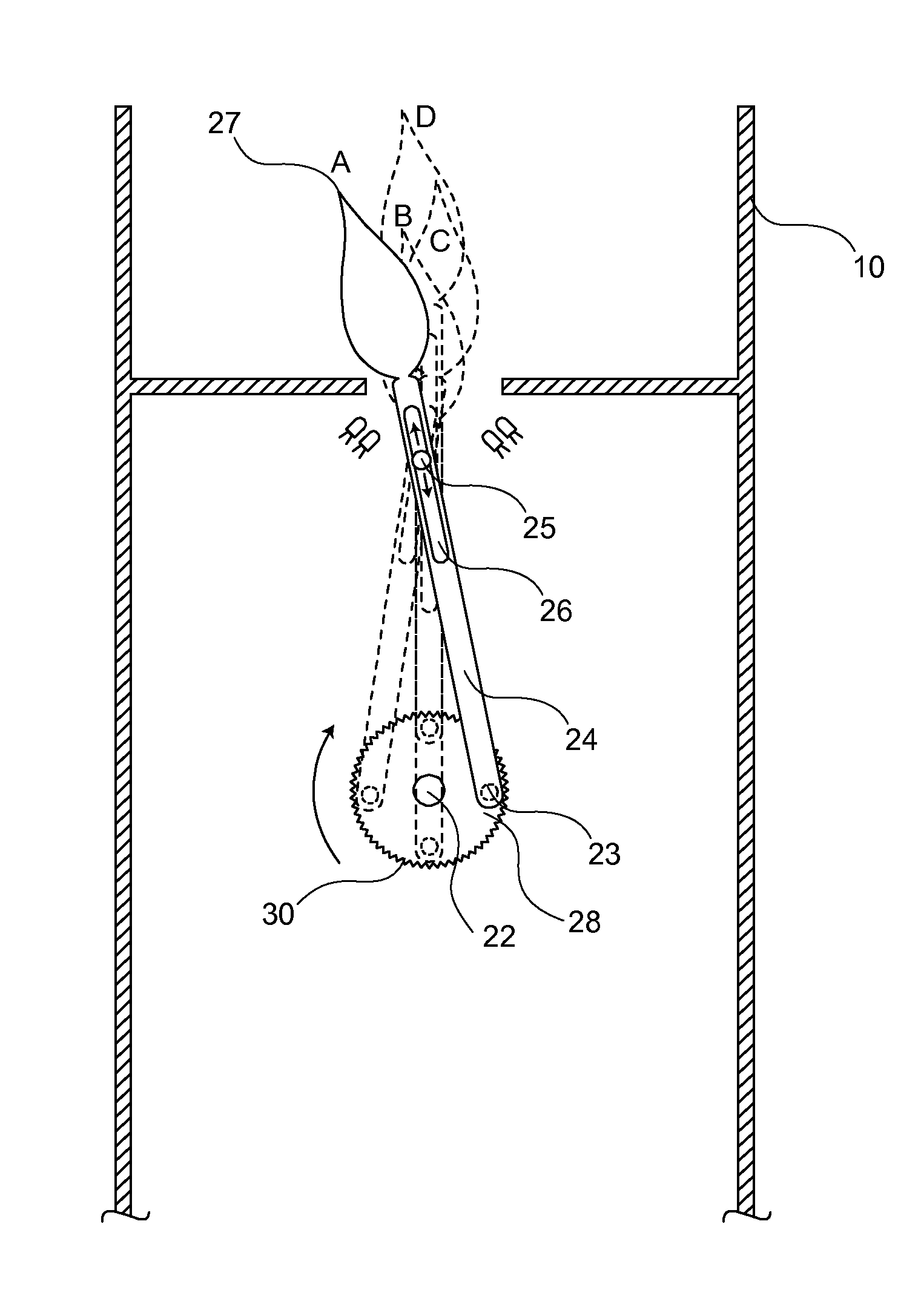
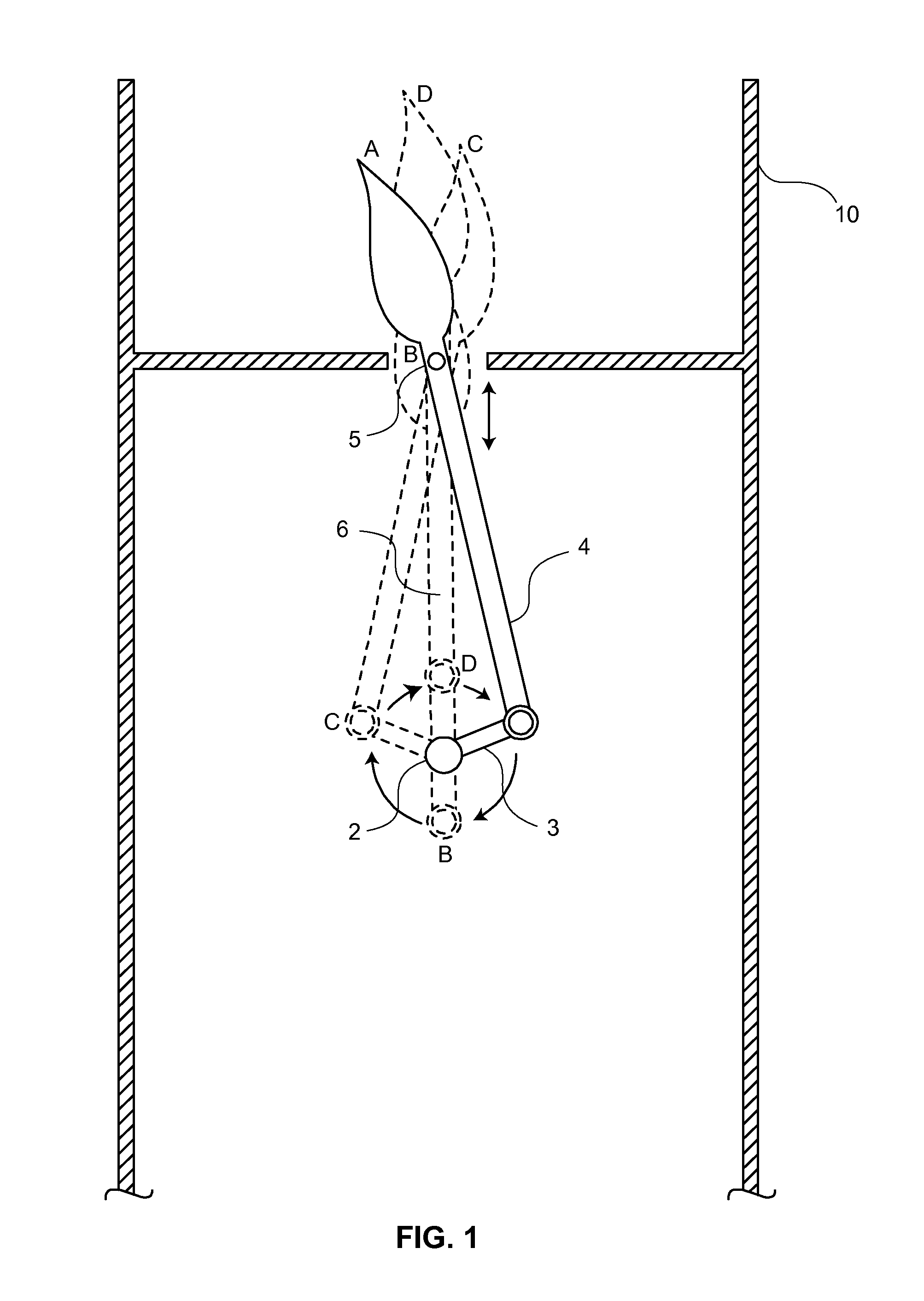
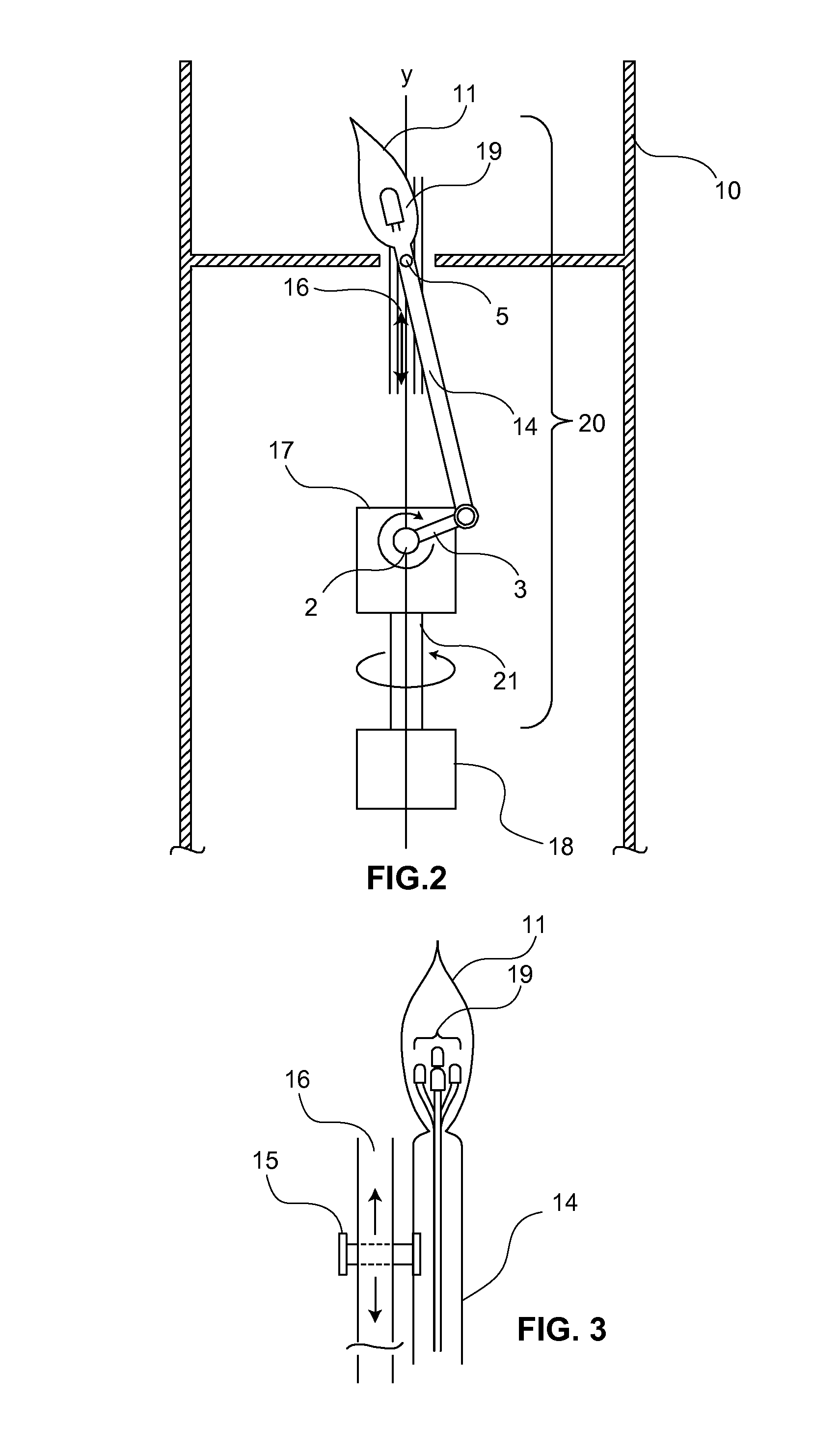
[0005]Present embodiments of the invention provide a flameless candle with a crank and connecting rod mechanism housed inside the candle for generating movement for a flame-shaped member. A motor rotationally drives a crank member connected to a rod that is coupled to the flame-shaped member, allowing the flame-shaped member to move in unity with the tilting and oscillating motion of the end of the connecting rod. A light source located apart from the flame-shaped member may project light onto the flame-shaped member. The flame-shaped member may house a light source that provides a flickering light. The crank, connecting rod, and flame-shaped member assembly may also move rotationally, providing further variation in movement. The oscillating and tilting motion of the flame-shaped member, coupled with the various light sources, provides a realistic appearance of a burning flame.

[0006]The above summary is not intended to limit the scope of the invention, or describe each embodiment, a...


PUM


Abstract

A flameless candle having a light-emitting flame-shaped member configured to move in a tilting or oscillating motion. The light-emitting flame-shaped member is joined to a connecting rod driven by a crank, the connecting rod having a pin received along a groove, or having a groove to house a pin, where the pin moves in a reciprocating motion causing the light-emitting flame-shaped member to move in a tilting and oscillating motion.

Description

FIELD OF THE INVENTION[0001]The present invention relates generally to lighting apparatuses and, more particularly, to an imitation candle with a moving, simulated flame.BACKGROUND OF THE INVENTION[0002]Electric lighting has not entirely replaced the desire to use flames and candles for providing light. Candles are appealing as decorations and for their gentle, low light. However, candles may be hazardous, capable of causing fires from the burning flame, and damage from hot wax. Other shortcomings of candles include how easily their flames are extinguished in the presence of wind and moisture, and how short of a period they last before their wax is consumed.[0003]Electric candles have been introduced to provide safe, electric-powered light while retaining the decorative and appealing qualities of candles. Small votive designs with a static bulb housed in hard plastic materials have been widely used. Recently, pillar designs with a housing made of wax have also been popular because t...

Claims


Application Information

Patent Timeline
Patent Type & Authority Applications(United States)
IPC IPC(8): F21S10/04F21V14/02F21S6/00
CPCF21S10/046F21S6/001F21W2121/00F21Y2101/02F21V14/02F21Y2115/10
Inventor JOHANNSSON, THROSTUR RUNAR
Owner SPALERO LTD
Why Eureka
Try Eureka