
Drawing apparatus and drawing method of drawing apparatus

a technology of drawing apparatus and drawing method, which is applied in the direction of typewriters, printing, other printing apparatus, etc., can solve the problems of difficult ejection of ink including coloring materials with large particle sizes, limited design that can be printed, and inability to achieve beautiful finish, so as to prevent blurring of image and shorten the amount of time necessary

Active Publication Date: 2015-12-31
CASIO COMPUTER CO LTD
View PDF2 Cites 3 Cited by
  • Summary
  • Abstract
  • Description
  • Claims
  • Application Information

AI Technical Summary

Benefits of technology

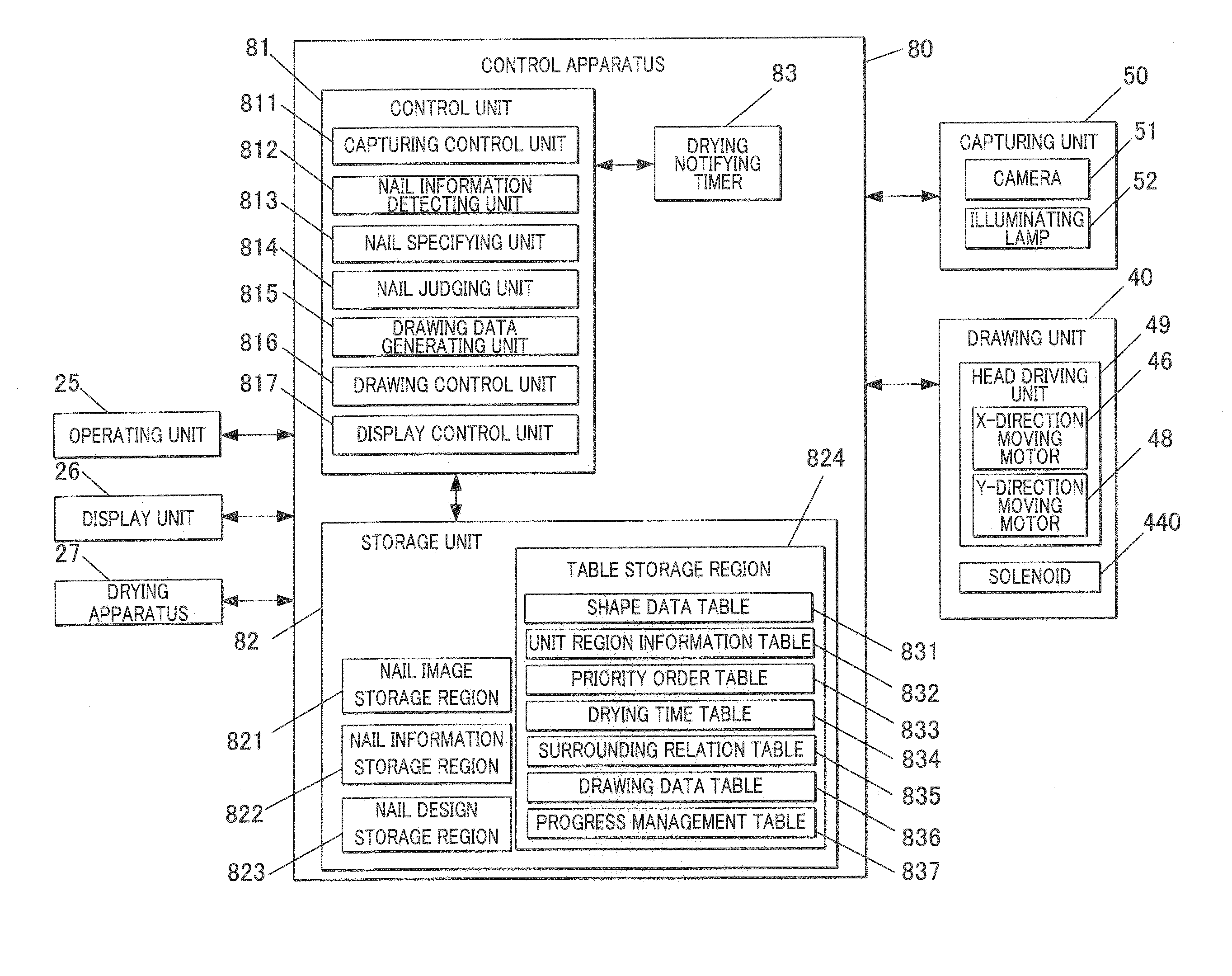
The present invention aims to provide a drawing apparatus and method that can prevent blurring of images and colors caused by different color ink being mixed while also reducing the amount of time required to draw on multiple nails. The apparatus uses a plurality of types of ink to draw target regions on the surfaces of multiple nails in a plurality of regions where the target regions in each nail are in contact with each other.

Problems solved by technology

However, it is difficult to eject ink including coloring material with large particle sizes as used in commercially available manicure from a drawing head of an ink-jet drawing apparatus.
Therefore, there are problems such as the design that can be printed being limited or the finish not being beautiful.
This results in a finish which is not beautiful.
Therefore, it takes longer to dry ink on nails than ink drawn on paper.
Since the time waiting for the ink to dry increases, a large amount of time is consumed for drawing.
Such waiting time becoming longer results in the drawing time becoming longer.
This becomes a problem when nail print is performed on a plurality of nails of a plurality of fingers, such as when nail print is performed on plurality of nails of plurality of fingers of one hand or both hands.

Method used


Image

  • Drawing apparatus and drawing method of drawing apparatus
  • Drawing apparatus and drawing method of drawing apparatus
  • Drawing apparatus and drawing method of drawing apparatus

Examples


Embodiment Construction

[0039]An embodiment of a drawing apparatus of the present embodiment is described with reference to the drawings. However, the scope of the present invention is not limited to the illustrated examples.

[0040]According to the drawing apparatus of the present embodiment, a nail is inserted in the drawing apparatus one nail at a time to draw on the nail of the finger and a plurality of fingers are successively switched so that drawing is performed on the nails of the plurality of fingers successively. According to the present embodiment, the drawing apparatus is a nail print apparatus.

[0041]According to the embodiments described below, technically preferred limitations are added to implement the present invention. However, the scope of the present invention is not limited to the embodiments and the illustrated examples described below.

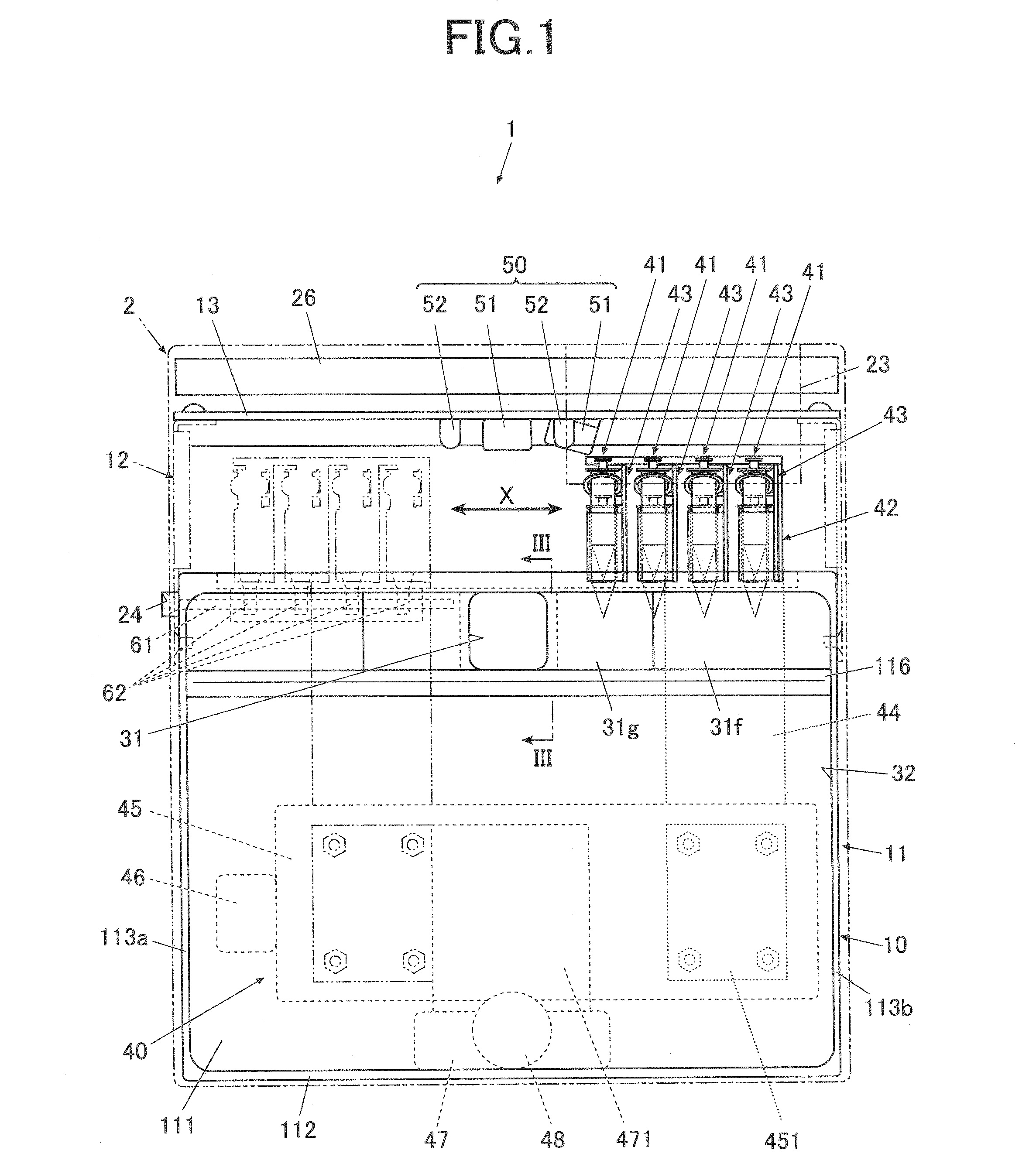
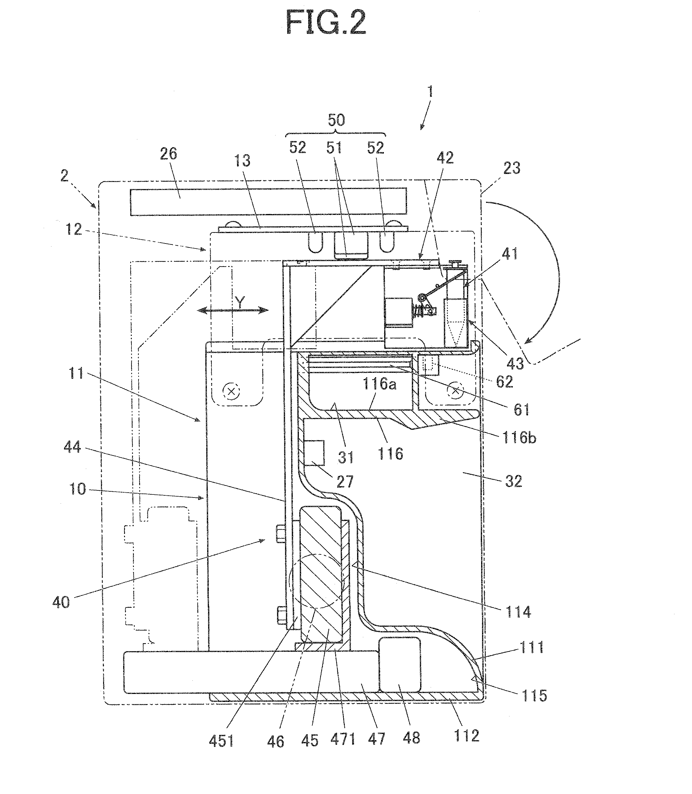
[0042]FIG. 1 is a front view of the nail print apparatus, and FIG. 2 is a side view showing an internal configuration from a cross sectional view of a por...


PUM


Abstract

A drawing apparatus and drawing method to perform drawing on a drawing target region are shown. The drawing apparatus includes a drawing unit and a control unit. The drawing target region is a surface of a plurality of nails and the nails include unit regions in contact with each other to be drawn with ink in different colors. The control unit includes a nail specifying unit which judges whether each of the unit regions is a dried unit region, a non-dried unit region, and a non-drawn unit region. Then, the nail specifying unit extracts the non-drawn unit region which is not in contact with the non-dried unit region as a specific unit region. The control unit also includes a drawing control unit which controls the drawing unit to perform the drawing on the specific unit region.

Description

CROSS-REFERENCE TO RELATED APPLICATIONS[0001]The present U.S. patent application claims priority under the Paris Convention of Japanese Patent Application No. 2014-133594 filed on Jun. 30, 2014 the entirety of which is incorporated herein by reference.BACKGROUND OF THE INVENTION[0002]1. Field of the Invention[0003]The present invention relates to a drawing apparatus and a drawing method used in the drawing apparatus.[0004]2. Description of the Related Art[0005]There is a conventionally known ink-jet printer (drawing apparatus) which sprays ink from a drawing head to print a nail design on a nail. Such drawing apparatus is described in, for example, Japanese Patent Application Laid-Open Publication No. 2003-534083.[0006]Printing on nails is easily possible at home if such drawing apparatuses are used.[0007]However, it is difficult to eject ink including coloring material with large particle sizes as used in commercially available manicure from a drawing head of an ink-jet drawing app...

Claims


Application Information

Patent Timeline
IPC IPC(8): B41J3/407
CPCB41J3/4073B41J3/407
Inventor YAMASAKI, SHUICHI
Owner CASIO COMPUTER CO LTD
Learn More