Imaging reader and method with tall field of view

a reader and tall field of view technology, applied in the field of indicia reading and electronic reader, can solve the problems of slowing down transaction processing and reducing productivity, difficult to grasp and pick up the wide housing with one hand, and difficult to blind-aiming the symbol, etc., to achieve easy handling, increase the vertical height of the presentation area, and easy to pick up the object.

Inactive Publication Date: 2007-08-02
SYMBOL TECH INC
View PDF1 Cites 10 Cited by
  • Summary
  • Abstract
  • Description
  • Claims
  • Application Information

AI Technical Summary

Benefits of technology

[0019] A two-dimensional, solid-state imager is mounted in the reader, and includes an array of image sensors operative for capturing light from a one-dimensional and / or a two-dimensional target passing through the presentation area over a field of view during the reading. Preferably, the array is a CCD array, but could be a CMOS array. The imager may be associated with a high-speed strobe illuminator under control of a controller to enable the image of the target to be acquired in a very short period of time, for example, on the order of 500 microseconds, so that the target image is not blurred even if there is relative motion between the imager and the target. The strobe illumination is preferably brighter than ambient illumination, especially close to the presentation area. The illumination can also be continuous. The imager captures light over an exposure time period, also under the control of the controller. A short exposure time also prevents image blurring.
[0021] Ideally, the housing of an imaging reader should be narrow enough for a user to easily pick it up to read large, heavy, or bulky products that cannot easily be brought to the reader. Rotating the solid-state imager allows the housing to be designed with a window of narrow width that in turn, allows the housing itself to be configured with a narrow width, thereby enabling easy handling.
[0022] Another advantage of a tall field of view, which is created by rotating the solid-state imager, stems from how the product is swiped. During the swipe mode, the user swipes the product bearing the symbol in a horizontal motion across the presentation area. As noted above, the symbol faces away from the user and, as a result of this blind aiming, some symbols fail to be read because they are not registered in the presentation area. Increasing the vertical height of the presentation area to accommodate a tall field of view reduces the chance of such reading failure, especially for elongated products where the symbol is positioned partially or fully above or below the presentation area during the swiping motion.
[0023] There is a group of documents such as driver's licenses, customer loyalty cards, membership cards, cash register paper receipts, credit / debit card transaction receipts requiring customer signatures, etc. that often are desired to be imaged as part of a point-of sale transaction, regardless of whether they bear a symbol. The image of each such document is captured by the solid-state imager by positioning each such document at the presentation area of the reader. A tall field of view and a tall window make it especially convenient to capture the entire image of each such document. A guide can be mounted at the front of the reader at the presentation area to make it easy to position each such document at the presentation area. Preferably, the guide is upwardly open along the vertical direction to enable easy insertion and removal of each such document along the vertical direction.

Problems solved by technology

In typical “blind-aiming” usage, it is not uncommon for the operator to repeatedly swipe or present a single symbol several times before the symbol is successfully read, thereby slowing down transaction processing and reducing productivity.
The blind-aiming of the symbol is made more difficult because the position and orientation of the symbol are variable.
Such a wide housing is not easy to grasp and pick up with one hand in order to read a symbol on a product that cannot easily be brought to the reader.
Another disadvantage of a wide and short field of view is that some symbols, especially on tall products, may be positioned partially or fully above or below the window and may miss being read through the window during either the presentation or the swipe mode, and fail to be read.

Method used


Image

  • Imaging reader and method with tall field of view
  • Imaging reader and method with tall field of view
  • Imaging reader and method with tall field of view

Examples


Embodiment Construction

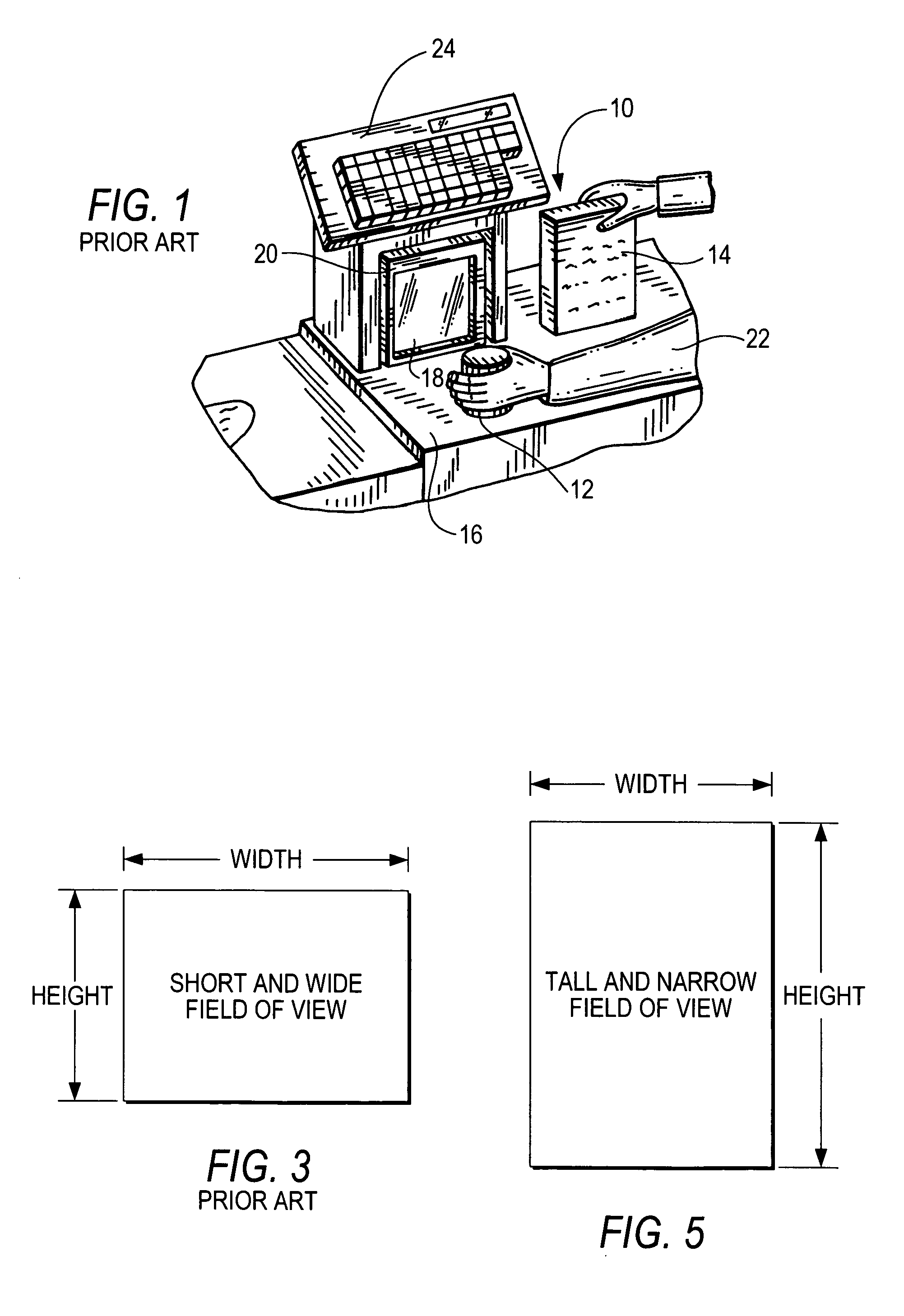
[0031] Reference numeral 10 in FIG. 1 generally identifies a workstation in accordance with the prior art for processing transactions and specifically a checkout counter at a retail site at which products, such as a can 12 or a box 14, each bearing a target symbol, are processed for purchase. The counter includes a countertop 16 across which the products are slid at a swipe speed past a vertical window 18 of a box-shaped vertical slot reader 20 mounted on the countertop 16. A checkout clerk or operator 22 is located at one side of the countertop, and the reader 20 is located at the opposite side. A cash / credit register 24 is located within easy reach of the operator.

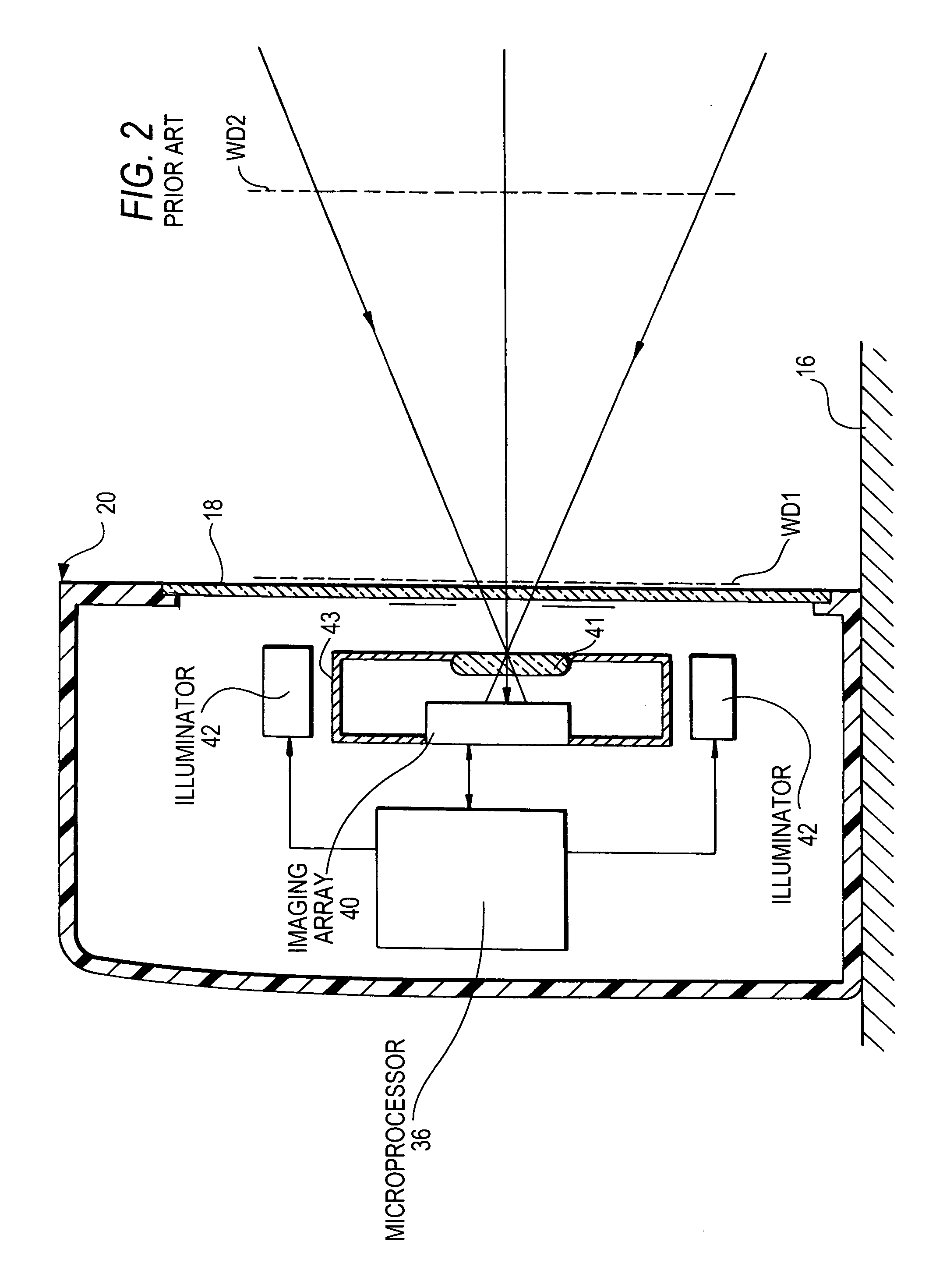
[0032] As shown in FIG. 2, in further accordance with the prior art, the vertical slot scanner generally includes an imager 40 and a focusing lens 41 mounted in an enclosure 43. The imager 40 is a solid-state device, for example, a CCD or a CMOS imager and has an array of addressable image sensors operative for capturin...


PUM


Abstract

A target is illuminated with light for image capture by a solid-state imager of an imaging reader over a tall field of view having an aspect ratio whose vertical dimension is larger than its horizontal dimension during image capture.

Description

BACKGROUND OF THE INVENTION [0001] 1. Field of the Invention [0002] The present invention generally relates to an electro-optical reader for reading indicia, especially two-dimensional indicia, by using a solid-state imager for image capture over a field of view having an aspect ratio whose vertical dimension is larger than its horizontal dimension. [0003] 2. Description of the Related Art [0004] Flat bed laser readers, also known as horizontal slot scanners, have been used to electro-optically read one-dimensional bar code symbols, particularly of the Universal Product Code (UPC) type, at a point-of-transaction workstation in supermarkets, warehouse clubs, department stores, and other kinds of retailers for many years. As exemplified by U.S. Pat. No. 5,059,779; No. 5,124,539; and No. 5,200,599, a single, horizontal window is set flush with, and built into, a horizontal countertop of the workstation. Products to be purchased bear an identifying symbol and are typically slid or swipe...

Claims


Application Information

Patent Timeline
Patent Type & Authority Applications(United States)
IPC IPC(8): G06K7/10
CPCG06K7/10732G06K7/10722
Inventor BARKAN, EDWARDDRYZMALA, MARK
Owner SYMBOL TECH INC
Why Eureka
Try Eureka