Sheet storing apparatus, post-processing apparatus and image forming system having the same

a technology of image forming system and sheet storing apparatus, which is applied in the direction of thin material processing, article separation, article delivery, etc., can solve the problems of image blurring, image blurring, image blurring, etc., and achieve the effect of preventing ink friction, low pressurization force, and high pressurization for

Active Publication Date: 2014-03-06
RISO KAGAKU CORP +1
View PDF7 Cites 9 Cited by
  • Summary
  • Abstract
  • Description
  • Claims
  • Application Information

AI Technical Summary

Benefits of technology

[0026]For example, when an image-formed sheet is discharged onto a stacked sheet through the sheet discharging port, the sheet discharging is performed by the conveying rollers at the sheet discharging port using the large-outer-diameter soft roll face with a low pressurization force. Accordingly, ink friction can be prevented from occurring owing to low engagement force between an introduced sheet and the upmost stacked sheet. Further, since the sheet face and roll face are pressure-contacted with a low pressurization force, a subsequent sheet is prevented from getting dirty with adhering of sheet ink onto the roll face.
[0027]Alternatively, when a sheet is stored at the stack tray at the downstream side as being nipped by the upper-lower pair of sheet discharging rollers, the sheet conveying is performed by the rollers using the small-outer-diameter hard roll face with a high pressurization force. Accordingly, the sheet can be reliably discharged to an accurate position on the tray.

Problems solved by technology

Here, following problems occur.
Mutual friction causes image blurring on freshly-fixed sheets fed from an image forming apparatus or the like.
Such image blurring frequently occurs when sheets are conveyed to the processing tray.
If fixing of an image on the sheet is insufficient, high contact pressure between the sheet and the rollers causes image blurring.
In addition, there arises a problem that a subsequent sheet gets dirty with ink adherent to the rollers.

Method used


Image

  • Sheet storing apparatus, post-processing apparatus and image forming system having the same
  • Sheet storing apparatus, post-processing apparatus and image forming system having the same
  • Sheet storing apparatus, post-processing apparatus and image forming system having the same

Examples


Embodiment Construction

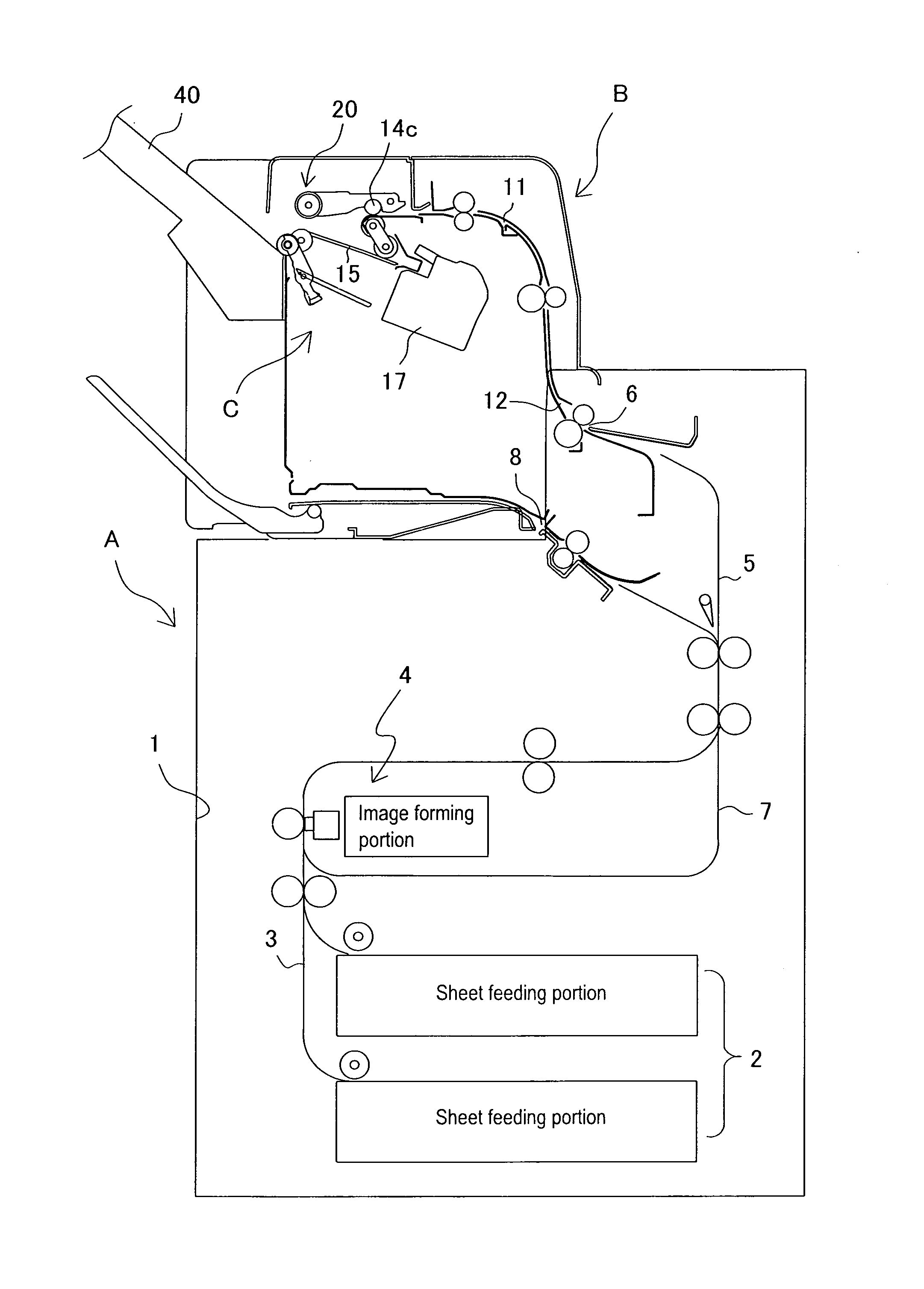
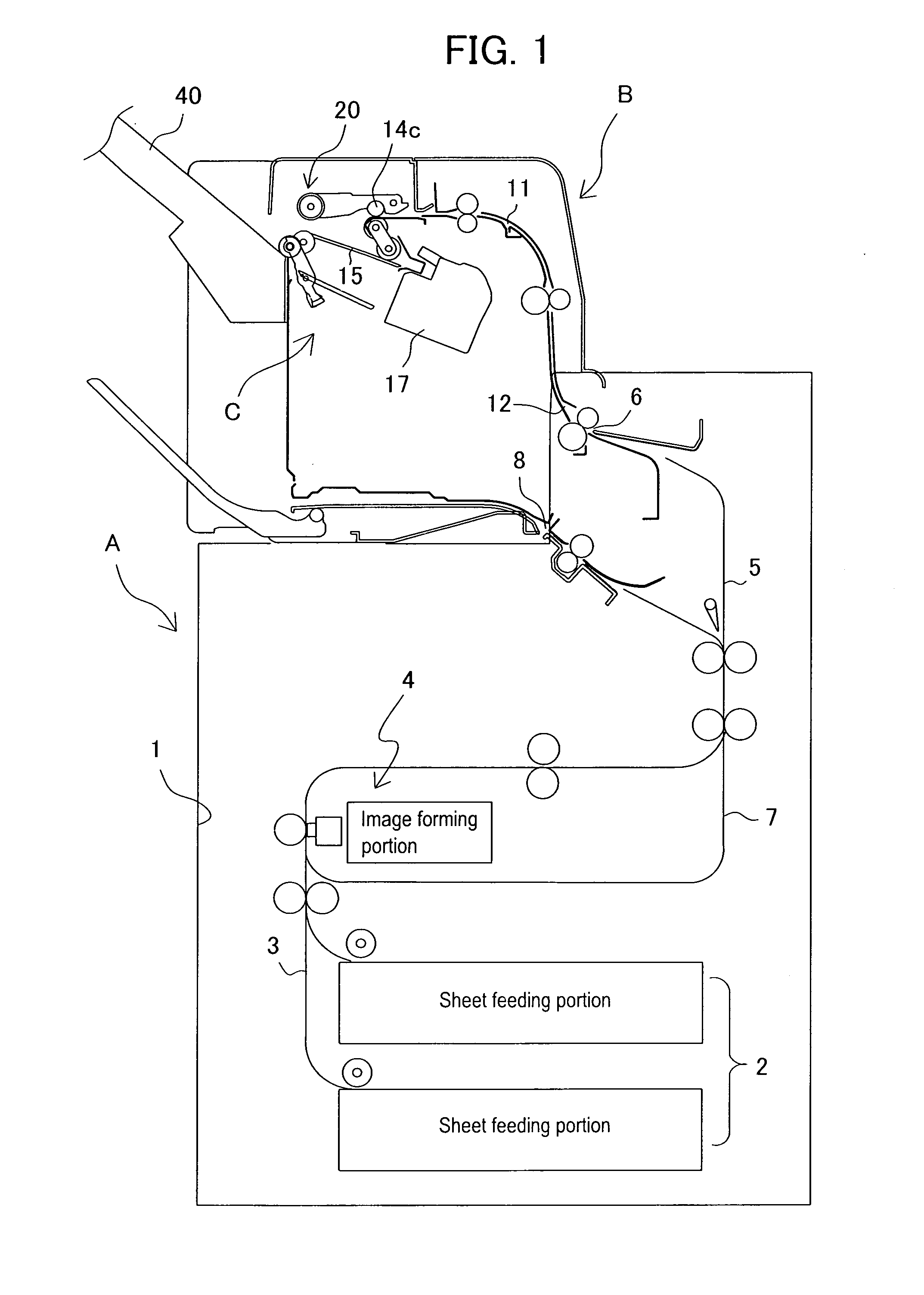
[0051]In the following, the present invention will be described in detail based on preferred embodiments illustrated in the drawings. FIG. 1 illustrates an image forming system. The image forming system includes an image forming apparatus (unit) A which forms an image on a sheet and a post-processing apparatus (unit) B which performs a post-process such as a binding process of collating and stacking sheets with images formed thereon. A sheet storing apparatus (unit) C according to the present invention is built into the post-processing apparatus B. In the following, description will be performed on the image forming apparatus and the post-processing apparatus in the order thereof.

[Image Forming Apparatus]

[0052]The image forming apparatus A illustrated in FIG. 1 is connected to an image managing device such as a computer and a network scanner (not illustrated). The image forming apparatus A forms an image on a specified sheet based on image data transferred from such a device and dis...


PUM

PropertyMeasurementUnit
inclination angleaaaaaaaaaa
outer circumferential diameteraaaaaaaaaa

Abstract

In a provided apparatus, an upper roller to be engaged with a sheet upper face and a lower roller to be engaged with a sheet lower face are arranged at a sheet discharging port in a manner capable of being pressure-contacted and being separated, the upper roller is formed with a large-diameter soft roll face and a small-diameter hard roll face, and a pressurization force of roller lifting-lowering means with which the upper roller is pressure-contacted to and is separated from the lower roller is switched to be high or low.

Description

BACKGROUND OF THE INVENTION[0001]1. Field of the Invention[0002]The present invention relates to a sheet storing apparatus which stores sheets fed from an image forming apparatus or the like at a downstream stack tray with or without performing a post-process thereon, and relates to improvement of a sheet discharging mechanism which conveys a sheet fed from a sheet discharging path toward the downstream stack tray.[0003]2. Description of Related Arts[0004]In general, in such a sheet storing apparatus, a pair of frictional rotors are arranged at a sheet discharging port and sheets are conveyed to the downstream side thereby. Belts, rollers, or the like have been adopted as the frictional rotors. For example, Japanese Patent Application Laid-Open No. 2009-035371 (Patent Document 1) discloses an apparatus in which a sheet fed to a sheet discharging path is conveyed by a pair of rollers arranged at a sheet discharging port selectively to a processing tray or a stack tray at the downstre...

Claims


Application Information

Patent Timeline
Patent Type & Authority Applications(United States)
IPC IPC(8): B65H39/00B65H31/00B65H3/06
CPCB65H39/00B65H31/00B65H3/06B65H29/14B65H31/10B65H31/26B65H31/3027B65H31/34B65H33/08B65H39/10B65H2301/4213B65H2404/1321B65H2404/1441B65H2404/1521B65H2404/166B65H2404/693B65H2511/20B65H2511/415B65H2511/51B65H2801/27B65H31/02B65H2301/4212B65H2405/11151B65H2511/15B65H2220/02B65H2220/11B65H2220/01B65H2220/03B65H5/068
Inventor MIMURA, HIDEKIIDEZUKI, KENTASANO, KENICHI
Owner RISO KAGAKU CORP
Why Eureka
Try Eureka