
V-ring seal with wipers

a technology of v-ring seals and wipers, which is applied in the field of v-ring seals, can solve the problems of affecting the integration of the seal between the sealing portion and the axial surface, and achieve the effect of preventing relative angular displacemen

Inactive Publication Date: 2015-12-31
AB SKF
View PDF2 Cites 6 Cited by
  • Summary
  • Abstract
  • Description
  • Claims
  • Application Information

AI Technical Summary

Benefits of technology

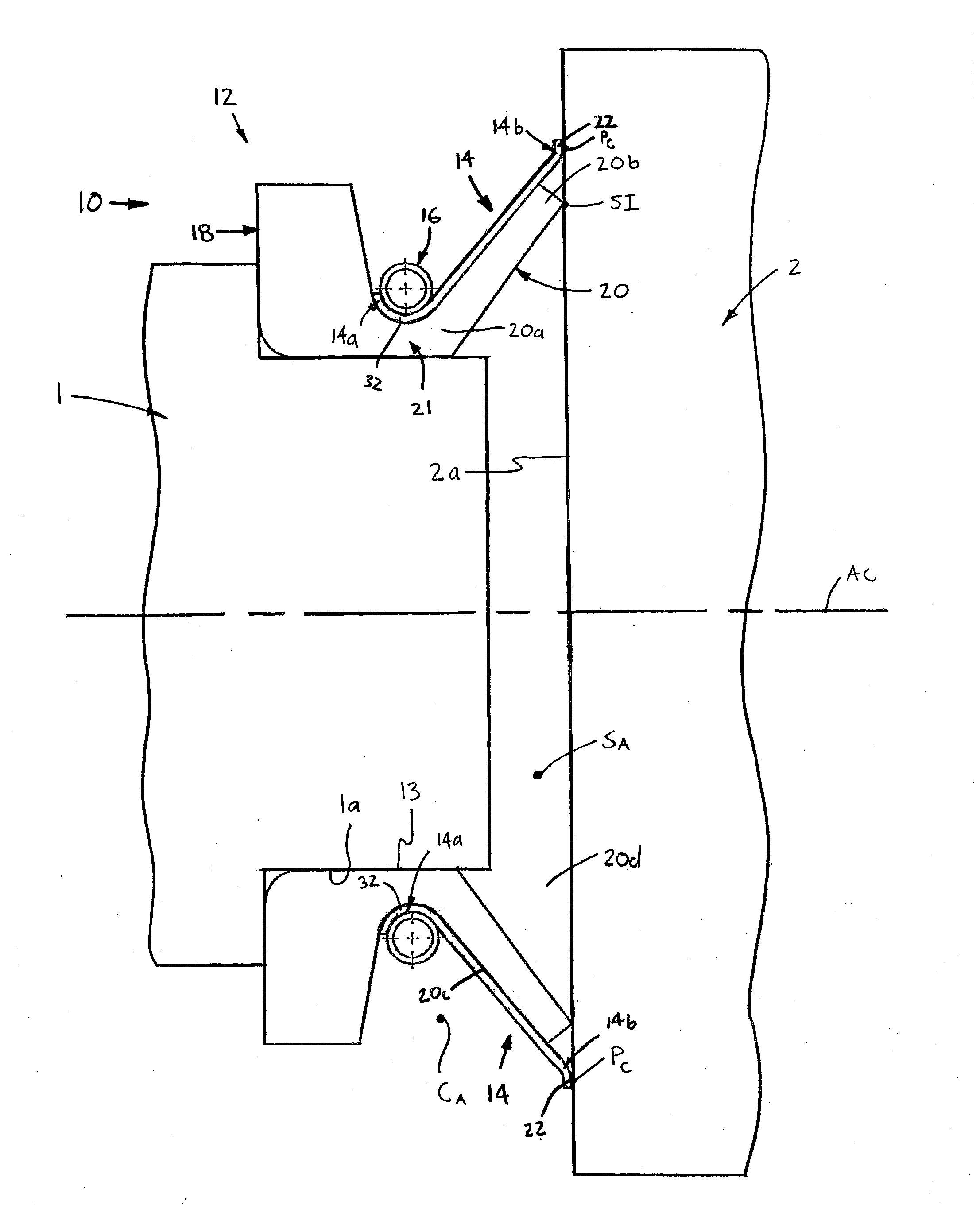
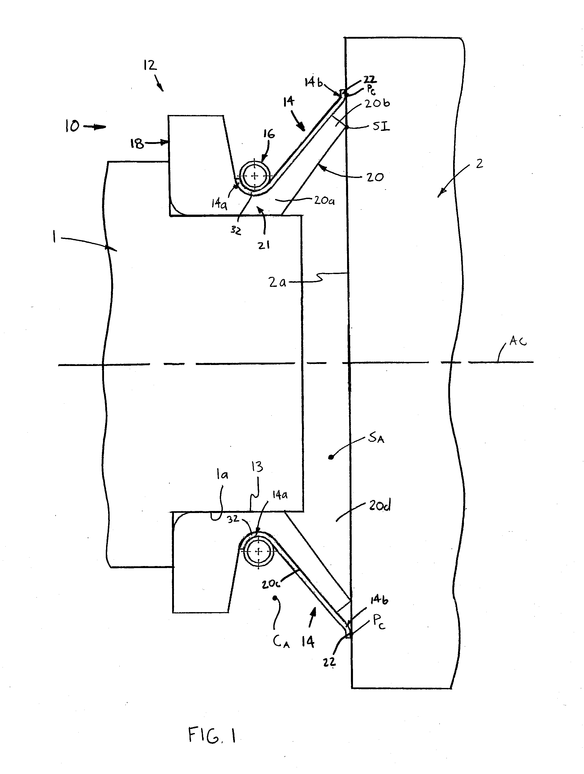
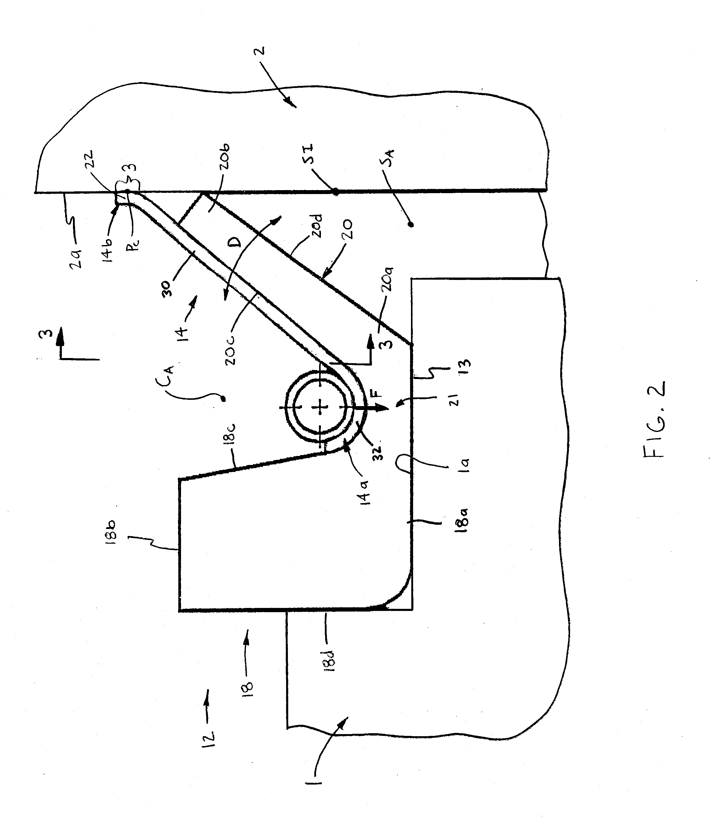
The present invention relates to a seal assembly for sealing a space between first and second members, at least one of which is a rotatable member. The seal assembly includes an elastomeric seal body with a base portion and a sealing portion that sealingly engage with the second member's axial surface to form an annular seal interface. A wiper is coupled with the seal body and is positioned to direct substances away from the sealing interface during rotation of the rotatable member. The seal assembly may also include a biasing member that exerts a radially-inward force on the seal body to prevent relative angular displacement between the seal body and the first member. A first and second wiper are coupled with the seal body and are positioned to engage the second member's axial surface at a position spaced radially outwardly from the sealing portion's outer end. The technical effect of the present invention is to provide an improved seal assembly for sealing a space between first and second members while preventing leaks and reducing wear on the seal body during use.

Problems solved by technology

Although such seals are generally effective, the integrity of the seal between the sealing portion and the axial surface can be affected when dust or other debris enters the interface between the sealing portion and surface.

Method used


Image

  • V-ring seal with wipers
  • V-ring seal with wipers
  • V-ring seal with wipers

Examples


Embodiment Construction

[0015]Certain terminology is used in the following description for convenience only and is not limiting. The words “inner”, “inwardly” and “outer”, “outwardly” refer to directions toward and away from, respectively, a designated centerline or a geometric center of an element being described, the particular meaning being readily apparent from the context of the description. Further, as used herein, the words “connected” and “coupled” are each intended to include direct connections between two members without any other members interposed therebetween and indirect connections between members in which one or more other members are interposed therebetween. The terminology includes the words specifically mentioned above, derivatives thereof, and words of similar import.

[0016]Referring now to the drawings in detail, wherein like numbers are used to indicate like elements throughout, there is shown in FIGS. 1-7 a seal assembly 10 for sealing a space SA between first and second members 1, 2,...


PUM


Abstract

A seal assembly is for sealing a space between first and second members and includes a generally annular elastomeric seal body disposed about an outer surface of the first member and extending circumferentially about a central axis. The body includes a base portion and a sealing portion, the sealing portion having an inner end integrally formed with the base portion and an outer, free end sealingly engageable with an axial surface of the second member so as to define a generally annular seal interface. A wiper is coupled with the seal body and has an engagement portion contactable with an axial surface of the second member at a position spaced radially outwardly from the sealing portion outer end. As such, the wiper engagement portion directs substances on the second member axial surface generally away from the sealing interface when the wiper contacts the substances during rotation of the rotatable member.

Description

BACKGROUND OF THE INVENTION[0001]The present invention relates to seals, and more particularly to V-ring seals for sealing against axial surfaces.[0002]V-ring axial seals are known and typically include an annular elastomeric body having a main body portion and a cantilever-like sealing portion extending from the main body portion. The seal body is disposed on a shaft or other mechanical member and the sealing portion engages with an axial surface of another, adjacent mechanical member so as to seal an axial space between the shaft / member and the other member.[0003]Although such seals are generally effective, the integrity of the seal between the sealing portion and the axial surface can be affected when dust or other debris enters the interface between the sealing portion and surface. That is, dust or debris may become disposed between the seal body sealing portion and the axial surface, which if accumulating in sufficient quantity, can create an opening for liquids or other substa...

Claims


Application Information

Patent Timeline
IPC IPC(8): F16J15/32
CPCF16J15/3232F16J15/3268F16J15/3456F16J15/3464
Inventor EPSHETSKY, YEFIMGILDEA, GREGORY G.MARTIN, MARIA CONCEPCION
Owner AB SKF
Learn More