Anti-rotation device for actuators

a technology of anti-rotation device and actuator, which is applied in the direction of linear bearings, mechanical devices, gearing, etc., can solve the problems of undesired wear on the contacting surface of the rails and/or the bar, and premature wear or even prevent relative displacement of the actuator member. , to prevent relative rotation prevent angular displacement

Inactive Publication Date: 2015-06-25
AKTIEBOLGAET SKF
View PDF7 Cites 5 Cited by
  • Summary
  • Abstract
  • Description
  • Claims
  • Application Information

AI Technical Summary

Benefits of technology

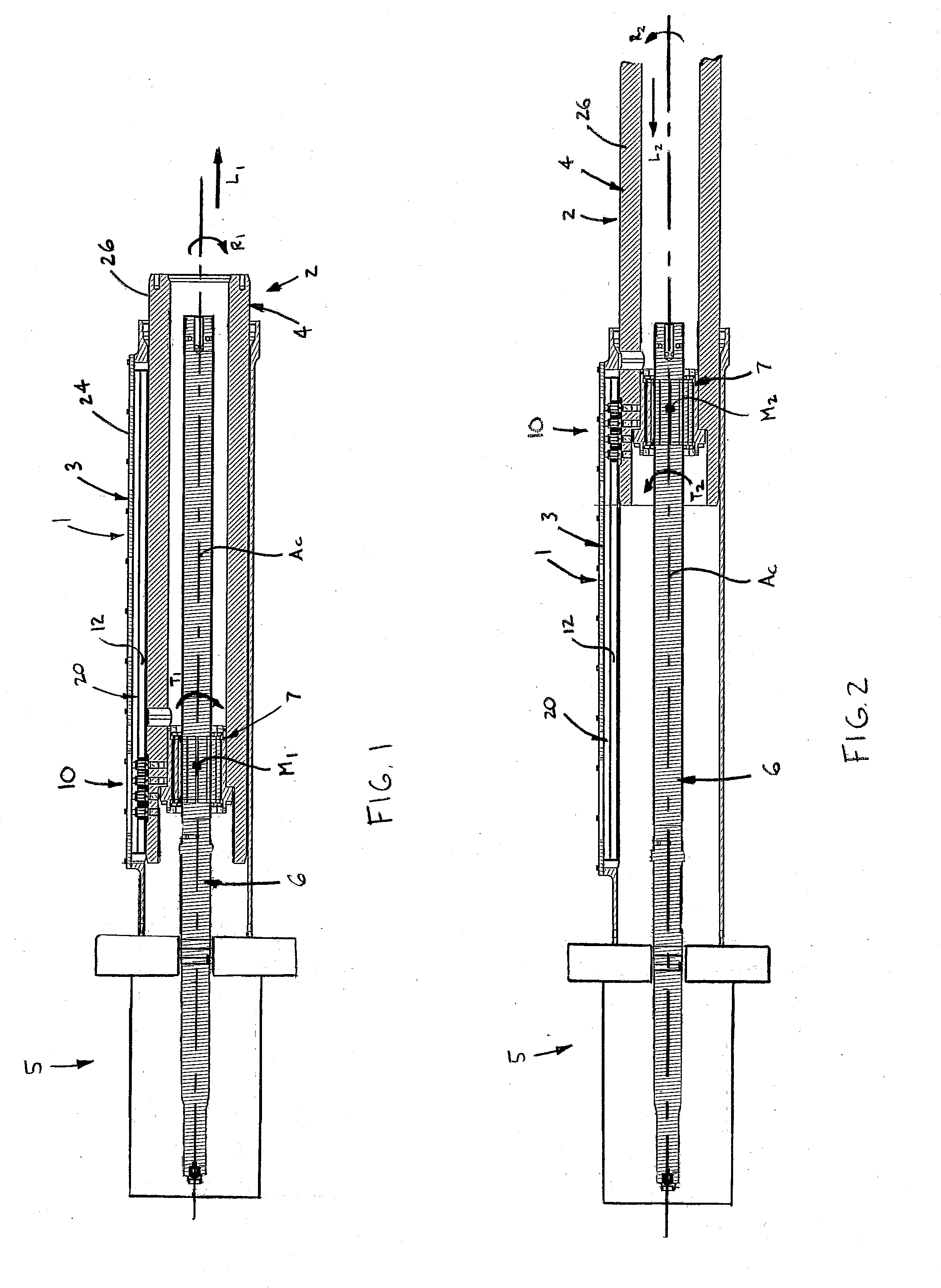
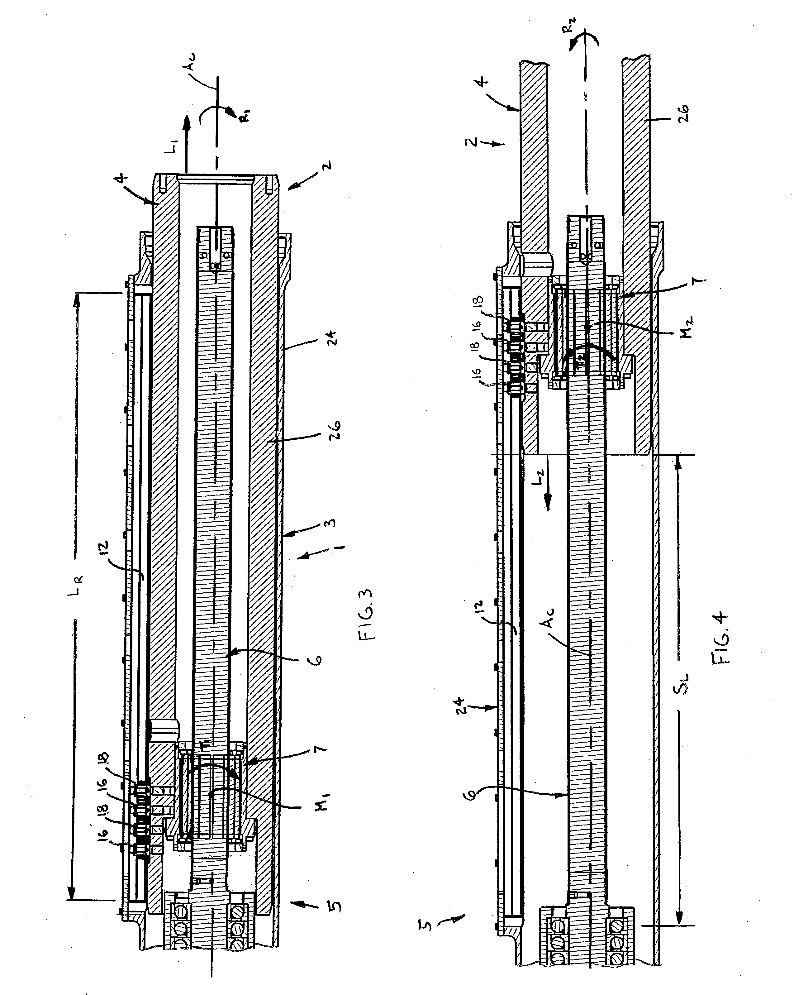
[0004]In one aspect, the present invention is an anti-rotation device for preventing relative rotation between first and second members. One of the first and second members is telescopingly disposed about the other one of the first and second members and at least one of the two members is linearly displaceable along a central axis extending through each of the two members. The anti-rotation device basically comprises first and second guide surfaces provided on the first member, the two guide surfaces extending generally parallel with each other and with the central axis. At least one first roller is connected with the second member and is rotatable about an axis located at a fixed position on the second member. The first roller is rollable along the first guide surface so as to prevent angular displacement between the first and second members when the displaceable one of the two members moves in a first direction along the axis. At least one second roller is connected with the second member and is rotatable about an axis located at a fixed position on the second member. The second roller is rollable along the second guide surface so as to prevent angular displacement between the first and second members when the displaceable one of the two members moves in a second, opposing direction along the axis.
[0005]In another aspect, the present invention is again an anti-rotation device for preventing relative rotation between first and second members. One of the first and second members is telescopingly disposed about the other one of the first and second members and at least one of the two members is linearly displaceable along a central axis extending through each of the two members. The anti-rotation device comprises first and second guide surfaces provided on the first member, the two guide surfaces extending generally parallel with each other and with the central axis. At least one first roller is disposed generally between the first and second guide surfaces, is connected with the second member and is rotatable about an axis located at a fixed position on the second member. The first roller is rollable along the first guide surface so as to prevent angular displacement between the first and second members when the displaceable one of the two members moves in a first direction along the axis. Further, the first roller is adjustably mounted on the second member such that the position of the first roller axis on the second member is variable to adjust a spacing distance between the first roller axis and the first guide surface. At least one second roller is disposed generally between the first and second guide surfaces, is connected with the second member and is rotatable about an axis located at a fixed position on the second member. The second roller is rollable along the second guide surface so as to prevent angular displacement between the first and second members when the displaceable one of the two members moves in a second, opposing direction along the axis.
[0006]In yet another aspect, the present invention is an assembly comprising first and second members and an anti-rotation device for preventing relative rotation between first and second members. One of the first and second members is telescopingly disposed about the other one of the first and second members and at least one of the two members is linearly displaceable along a central axis extending through each of the two members. The anti-rotation device includes first and second guide surfaces provided on the first member, the two guide surfaces extending generally parallel with each other and with the central axis. At least one first roller is connected with the second member and is rotatable about an axis located at a fixed position on the second member. The first roller is rollable along the first guide surface so as to prevent angular displacement between the first and second members when the displaceable one of the two members moves in a first direction along the axis. Further, at least one second roller is connected with the second member and rotatable about an axis located at a fixed position on the second member, the second roller being rollable along the second guide surface so as to prevent angular displacement between the first and second members when the displaceable one of the two members moves in a second, opposing direction along the axis.

Problems solved by technology

Thus, this torque must be counteracted or the displaceable member may bind within the other member, or at least cause premature wear on contacting surfaces of the two actuator members.
The rails slide along contacting surfaces of the bar and effectively prevent rotation, but may have undesired wear on the contacting surfaces of the rails and / or the bar.
However, excessive dimensional variations between the two actuator members due to overlarge manufacturing tolerances may cause the balls to jam within the associated grooves and lead to premature wear or even prevent relative displacement of the actuator members.

Method used


Image

  • Anti-rotation device for actuators
  • Anti-rotation device for actuators
  • Anti-rotation device for actuators

Examples


Embodiment Construction

[0028]Certain terminology is used in the following description for convenience only and is not limiting. The words “inner”, “inwardly” and “outer”, “outwardly” refer to directions toward and away from, respectively, a designated centerline or a geometric center of an element being described, the particular meaning being readily apparent from the context of the description. Further, as used herein, the words “connected” and “coupled” are each intended to include direct connections between two members without any other members interposed therebetween and indirect connections between members in which one or more other members are interposed therebetween. The terminology includes the words specifically mentioned above, derivatives thereof, and words of similar import.

[0029]Referring now to the drawings in detail, wherein like numbers are used to indicate like elements throughout, there is shown in FIGS. 1-20 an anti-rotation device 10 for preventing relative rotation between first and s...


PUM


Abstract

An anti-rotation device prevents relative rotation between first and second members, one member being telescopingly disposed about the other and at least one member being linearly displaceable along a central axis. First and second guide surfaces are provided on the first member and extend generally parallel with each other and the central axis. First and second rollers are connected with the second member and are each rotatable about an adjustably fixed axis on the second member. The first roller is rollable along the first guide surface to prevent angular displacement between the two members when the displaceable member moves in a first direction and the second roller is rollable along the second guide surface to prevent angular displacement between the two members when the displaceable member moves in an opposing direction. The contact between the rollers and guide surfaces provide a radial degree of freedom to the anti-rotation device.

Description

BACKGROUND OF THE INVENTION[0001]The present invention relates to actuators, and more particularly to anti-rotation devices for linear actuators.[0002]Certain linear actuators include first and second members (e.g., tubes, rods, etc.) in which one member is telescopingly disposed within the other member. Often, a motor driven power screw drives a nut coupled with one of the two members so as to cause the connected member to slidingly displace relative to the other member. When the nut is restrained from rotating and only displaces linearly along the screw, a torque is exerted on the nut which tends to angularly bias the member coupled with the nut relative to the other member. Thus, this torque must be counteracted or the displaceable member may bind within the other member, or at least cause premature wear on contacting surfaces of the two actuator members.[0003]One known approach to resist the torque applied to the nut is to provide an elongated rectangular bar mounted on one actu...

Claims


Application Information

Patent Timeline
Patent Type & Authority Applications(United States)
IPC IPC(8): F16H25/12
CPCF16H25/12F16H25/20F16C13/006F16C23/10F16C29/045F16H2025/204Y10T74/18704
Inventor LECLUSE, SEBASTIENDUBUS, JEROMELEE, MARCUS HONG YEOWGROVE, FRANSCHANDILA, PARVEENBOCH, CHRISTIAN
Owner AKTIEBOLGAET SKF
Why Eureka
Try Eureka