Drilling Accessory

a technology for accessories and drill bits, applied in the direction of drilling/boring measurement devices, portable drilling machines, manufacturing tools, etc., can solve the problems of skewing the drilling of holes, injury hazards, and inaccurate guided drill bits of smaller sizes, so as to avoid injury

Active Publication Date: 2020-10-01
DRILBY CC
View PDF0 Cites 0 Cited by
  • Summary
  • Abstract
  • Description
  • Claims
  • Application Information

AI Technical Summary

Benefits of technology

[0034]In the depressed condition (i.e. in contact with the surface of the Target Object), the contact lip, together with points on each opposing peripheral edge of the planar support surface portion, lying on an axis extending diametrically across the second through hole, are each: (i) in contact with the Target Object; and (ii) co-planar relative to one another; thereby to prevent angular displacement of the drilling accessory relative to the Target Object in such depressed condition. It will be appreciated that this provides the drilling accessory with stability against the Target Object.
[0035]Preferably, the side of the base making contact in use with the surface of the Target Object is also rubbery and tacky in nature. This ensures a firm grip between the drilling accessory and the surface of the Target Object, thereby providing stability both for purposes of accurate drilling and to avoid injury.

Problems solved by technology

Although the Silverline-type collectors do to some extent assist the user in orientating the drill bit passing through such through holes correctly with the Target Object, they are typically manufactured with larger single-sized-through holes through which a number of drill bits of differing sizes can pass, with the result that drill bits of smaller sizes are not accurately guided, having the consequence of skew holes being drilled.
Other disadvantages of the Silverline-type collectors are:their Target Object contacting face is generally made from a plastic-like material incapable of gripping and sealing effectively against the surface of the Target Object, particularly stippled plastered walls, resulting in some of the dust falling out between the Target Object and the collector before it can reach the dust collecting cavity; andthe Target Object contacting face area is often very small and consequently unstable, resulting in skew drilling of holes and posing an injury hazard.
The first of such disadvantages is that the collector appears to have to be physically attached to the power drill itself by way of a spring-loaded connecting rod, and cannot seemingly be utilised separately as purely a hand-held device.
The second disadvantage, flowing from the first disadvantage, is a stability problem arising as a result of the sealing member standing proud of the second face of the container and being the only portion of the collector in direct contact with the Target Object.
The third disadvantage of the ZAHLMANN Collector is the radially outwardly tapering bore defined by the sealing member as it extends from the through hole in the container towards a contact lip at a free end of the seal member, which in use contacts the Target Object being drilled.
In use, the sealing member is squeezed and pinched between the Target Object surface and a raised rim portion of the container defining the through hole, which may cause damage to such sealing member, as well as to the Target Object surface.
Furthermore, and in use in respect of a vertical Target Object surface, the tapering bore defines a downwardly sloping surface along which dust under the force of gravity would be forced to move out of the collector and thereby cause unnecessary mess.

Method used


Image

  • Drilling Accessory
  • Drilling Accessory
  • Drilling Accessory

Examples


Embodiment Construction

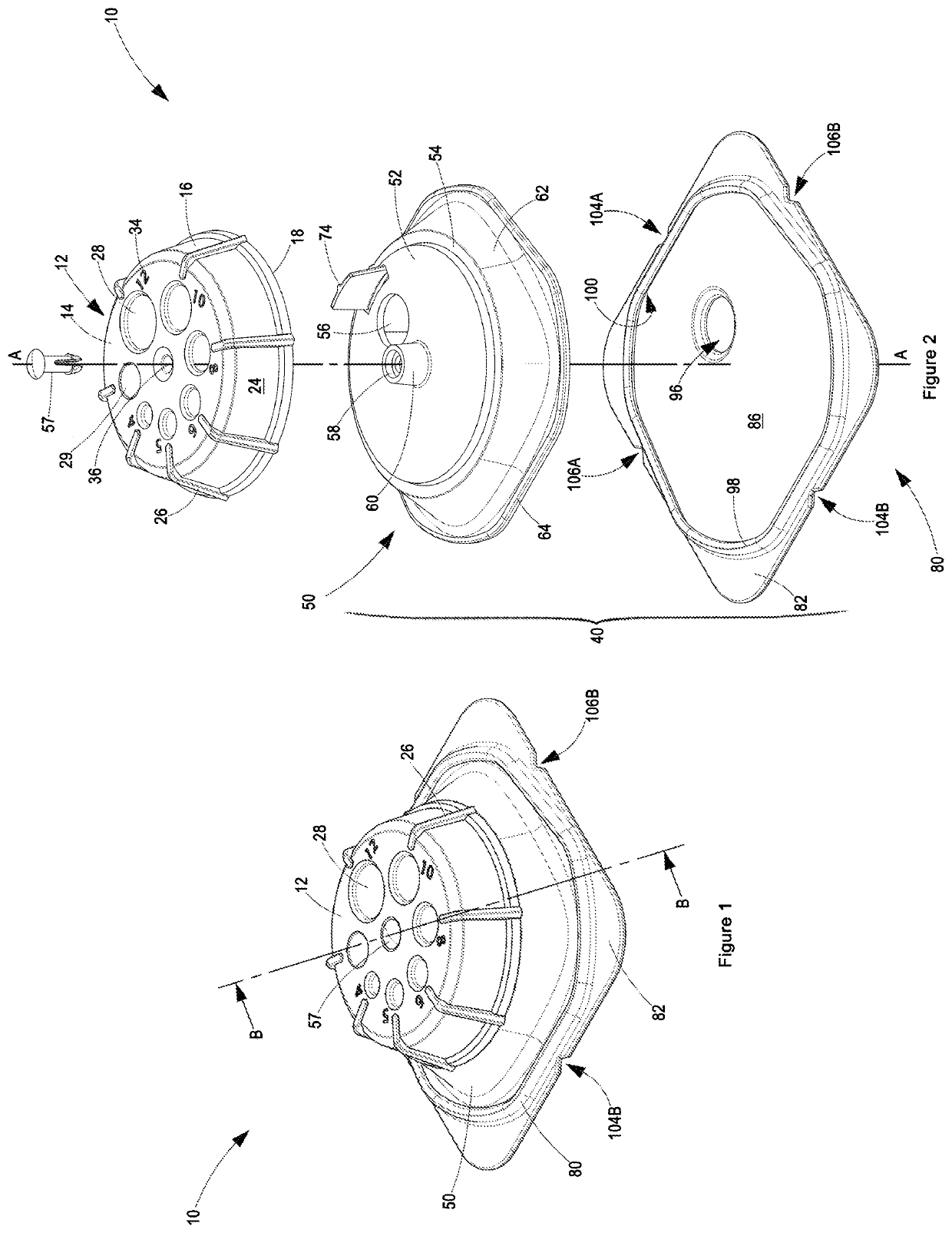
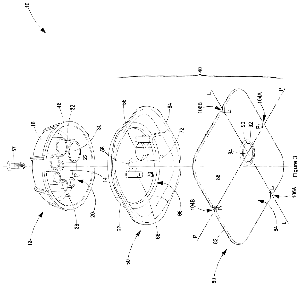
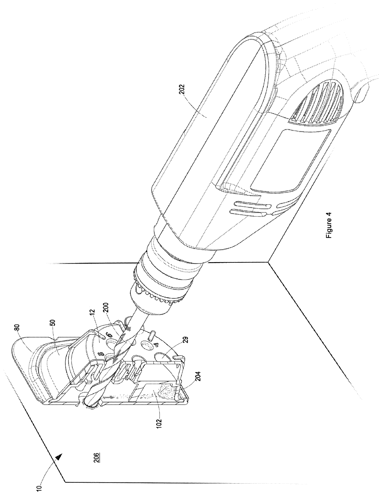
[0051]A drilling accessory according to a preferred embodiment of the invention is designated generally in the accompanying Figures by reference numeral 10. With reference to FIG. 1 and FIG. 2, the drilling accessory incorporates a cap 12 and a container 40, the latter comprising a cover member 50 and a base member 80 being connectible to one another.

[0052]With reference also to FIG. 3, the cap 12 is substantially cup-shaped comprising an end wall 14 and sidewalls 16 extending from the end wall 14 such that edges 18 of the sidewalls 16 distal the end wall 14 define an opening 20 into an inner cavity or side 22 of the cap 12.

[0053]The inner side 22 of the cap 12 is sized for receiving at least a portion of a cap-engaging end 52 of the container 40, where the cap-engaging end 52 of the container 40 is an end wall 52 of the cup-shaped cover member 50. An outer side 24 of the cap 12 bears gripping formations 26 projecting outwardly from the sidewalls 16 and partially from the end wall 1...


PUM

PropertyMeasurementUnit
sizeaaaaaaaaaa
areaaaaaaaaaaa
sizesaaaaaaaaaa

Abstract

THIS invention relates to a drilling accessory for a power drill drilling accessory that assists the operator of the power drill to correctly align and orientate the drill bit of the power drill with the target object, and collects the dust and/or debris arising from such drilling. The drilling accessory includes a cap having a plurality of differently sized guide holes and a container to which the cap is pivotally connected. The container comprises a first through hole, which on rotation of the cap relative to the container, enables the first through hole to be aligned with the require guide hole thereby to allow a drill bit to pass therethrough. The container further comprises a base having a planar support surface portion and a seal portion protruding outwardly from the support surface portion towards a contact lip, which contact lip defines a second through hole coaxially aligned with the first through hole. The protruding seal portion defines a bore therein tapering radially inwardly from the planar surface portion of the base towards the contact lip, which in use biases the contact lip into sealing engagement with the target object to efficiently collect dust and debris, with substantially the entire planar support surface portion contacting the target object thereby to provide a stability for drilling straight holes.

Description

BACKGROUND OF THE INVENTION[0001]THIS invention is a drilling accessory, more specifically, a power drill drilling accessory that:[0002]assists the operator of the power drill to correctly align and orientate the drill bit of the power drill with the target object being drilled (e.g. a wall) (hereinafter referred to as “the Target Object”) so as to thereby ensure drilling accuracy; and[0003]collects the dust and / or debris arising from such drilling and thereby greatly reduces dust and mess so as to: (i) prevent any dirtying or marking or staining of walls, floors and / or carpets occasioned by such dust and / or debris; and (ii) eliminate the need to clean up such dust and / or debris after drilling.[0004]There are various existing kinds of drill dust collectors. One type of such collector is marketed under the name “Silverline Drill Dust Collector” (hereinafter referred to as “the Silverline Collector”), which collector is in the form of a container defining a cavity for collecting and h...

Claims


Application Information

Patent Timeline
Patent Type & Authority Applications(United States)
IPC IPC(8): B23B49/02B23B47/28
CPCB23B49/02B23B47/28B23Q11/0071B23Q11/08B23B2247/12B23Q11/0053B23B45/003
Inventor ANDERSON, MARK WILLIAMDE JONGH, ANDREW COLYNANDERSON, MICHAEL ROBB
Owner DRILBY CC
Why Eureka
Try Eureka