Retro-fittable vehicle lock

a vehicle lock and retrofitting technology, applied in the field of vehicle security, can solve the problems of affecting the safety of the vehicle, requiring fairly drastic or significant changes to the vehicle, and unable to find a way to bypass or circumvent these standards

Pending Publication Date: 2021-04-29
HARDCORE AUTOMOTIVE LOCKING TECH PTY LTD
View PDF8 Cites 1 Cited by
  • Summary
  • Abstract
  • Description
  • Claims
  • Application Information

AI Technical Summary

Benefits of technology

[0028]an actuator which is drivingly connected to the locking member and is configured to displace the locking member between an open position, in which the rotor is free to rotate together with the drive flange about a drive axis, and the locked position, in which the locking member engages the rotor and prevents angular displacement of the rotor about the drive axis.

Problems solved by technology

Despite these measures being in place, thieves often still manage to find ways of bypassing or circumventing these standard, manufacturer-specified vehicle safety measures.
A drawback associated with after-market innovations is that, in many instances, fairly drastic or significant alterations have to be made to the vehicle in order to retrofit these security devices.
Inevitably, as time passes, weaknesses with these devices are identified and exploited by thieves.
For example, weaknesses associated with existing devices may include ease of tampering with the device, ability to interrupt power to the device, ability to bypass the device completely, or, in worst case scenarios, ability to tow away the vehicle, despite the presence of a properly functioning security device to a remote location where the device can be effectively disarmed and / or removed.

Method used


Image

  • Retro-fittable vehicle lock
  • Retro-fittable vehicle lock
  • Retro-fittable vehicle lock

Examples


Embodiment Construction

[0048]The following description of the invention is provided as an enabling teaching of the invention. Those skilled in the relevant art will recognise that many changes can be made to the embodiments described, while still attaining the beneficial results of the present invention. It will also be apparent that some of the desired benefits of the present invention can be attained by selecting some of the features of the present invention without utilising other features. Accordingly, those skilled in the art will recognise that modifications and adaptations to the present invention are possible and can even be desirable in certain circumstances, and are a part of the present invention. Thus, the following description is provided as illustrative of the principles of the present invention and not a limitation thereof.

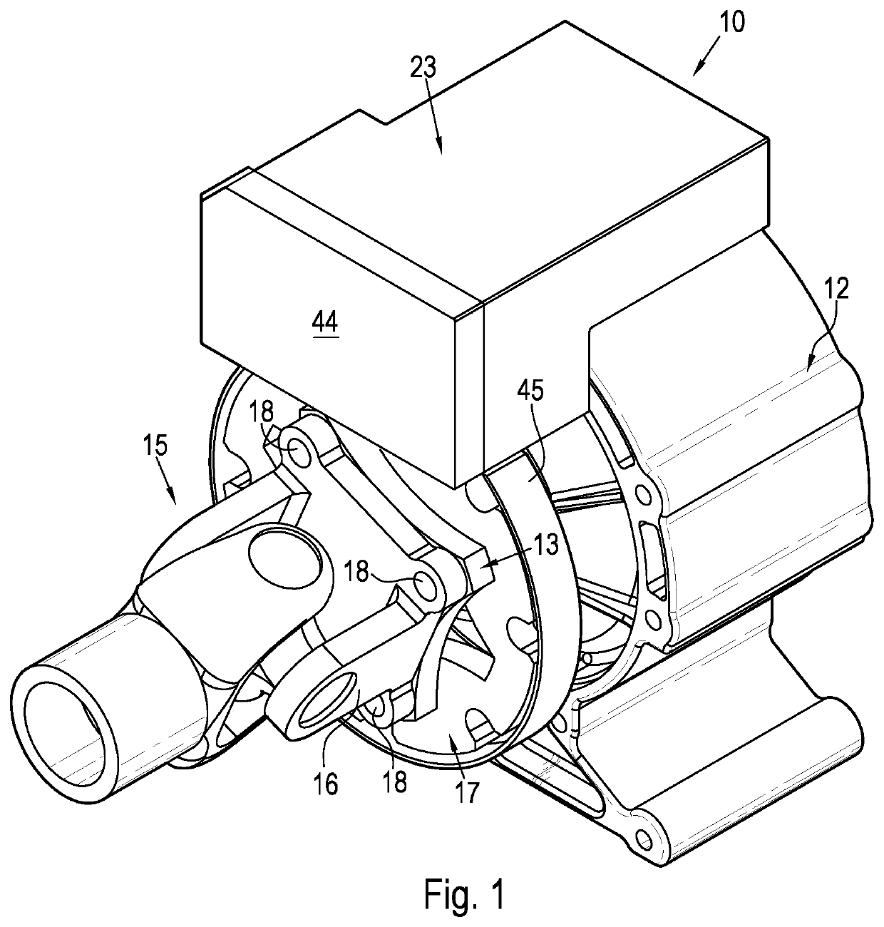
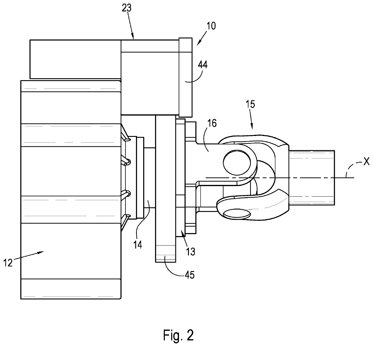
[0049]In the figures, reference numeral 10 refers generally to a driveshaft lock in accordance with one aspect of the invention. The driveshaft lock 10 is configured to b...


PUM


Abstract

The invention relates to a driveshaft lock (10) and to a method (50) of retrofitting the driveshaft lock to a vehicle. The driveshaft lock (10) includes a rotor (17) which defines a star-shaped central aperture (20) which is configured to receive a non-circular, peripheral profile of a drive flange (13) therethrough such that the rotor (17) is configured to piggyback on the drive flange (13). The lock (10) includes a locking member (21) which is configured selectively to engage the rotor (17) in order to lock the rotor in position and prevent angular displacement thereof. Amongst other steps, the method (50) includes aligning the aperture (20) of the rotor with the profile of the drive flange, passing the rotor over the drive flange, rotating the rotor relative to the drive flange, and securing the rotor to the drive flange for rotation together with the drive flange, piggyback-style.

Description

FIELD OF INVENTION[0001]This invention relates to vehicle security. More specifically, it relates to a vehicle driveshaft lock which is configured to be retrofitted to a vehicle.BACKGROUND OF INVENTION[0002]All new vehicles come standard with some form of vehicle security or alarm system which usually comprises a central door locking system operated using a remote control. Modern vehicles usually also include some form of electronic immobiliser which disables certain functions of the vehicle in order to prevent unauthorised use of the vehicle. Despite these measures being in place, thieves often still manage to find ways of bypassing or circumventing these standard, manufacturer-specified vehicle safety measures.[0003]Accordingly, innovators have tried to come up with innovative after-market security solutions in order to fortify vehicles against theft. These innovations include gear locks, steering or pedal locks, tracking devices, and electronic immobilisers, just to name a few. A...

Claims


Application Information

Patent Timeline
Patent Type & Authority Applications(United States)
IPC IPC(8): B60R25/06F16H63/34F16H63/36
CPCB60R25/06B60R2025/0415F16H63/36F16H63/3408F16H63/34B60R25/04
Inventor TALJAARD, PHILIPPUS PETRUS ERASMUS
Owner HARDCORE AUTOMOTIVE LOCKING TECH PTY LTD
Why Eureka
Try Eureka