
Semiconductor device having vertical channel and air gap, and method of manufacturing thereof

Active Publication Date: 2015-12-31
SAMSUNG ELECTRONICS CO LTD
View PDF3 Cites 158 Cited by
  • Summary
  • Abstract
  • Description
  • Claims
  • Application Information

AI Technical Summary

Benefits of technology

The present invention provides a nonvolatile memory device with a stacked structure that includes multiple word lines and air gaps interposed between them. Each memory cell includes a blocking pattern, a charge trap pattern, and a tunneling insulating pattern. A contiguous tunneling insulating pattern is interposed between the stacked structure and the channel structure. The method of forming the memory device involves staking insulating layers alternately to form the stacked structure and then removing certain layers to form the word lines and air gaps. The technical effects of the invention include a reduction in the size of the memory device and improved efficiency in the use of space.

Problems solved by technology

As the number of stacked cells increases, the thickness of the stacked cells increases to the extent that an etching process is difficult.
As the thickness of the stacked cells reduces, an operational speed thereof may be lowered due to coupling capacitance between word lines to the extent that a read operation error may occur.

Method used


Image

  • Semiconductor device having vertical channel and air gap, and method of manufacturing thereof
  • Semiconductor device having vertical channel and air gap, and method of manufacturing thereof
  • Semiconductor device having vertical channel and air gap, and method of manufacturing thereof

Examples


Embodiment Construction

[0015]Exemplary embodiments of the inventive concept will be described below in detail with reference to the accompanying drawings. However, the inventive concept may be embodied in different forms and should not be construed as limited to the embodiments set forth herein. In the drawings, the thickness of layers and regions may be exaggerated for clarity. It will also be understood that when an element is referred to as being “on” another element or substrate, it may be directly on the other element or substrate, or intervening layers may also be present. It will also be understood that when an element is referred to as being “coupled to” or “connected to” another element, it may be directly coupled to or connected to the other element, or intervening elements may also be present. Like reference numerals may refer to the like elements throughout the specification and drawings.

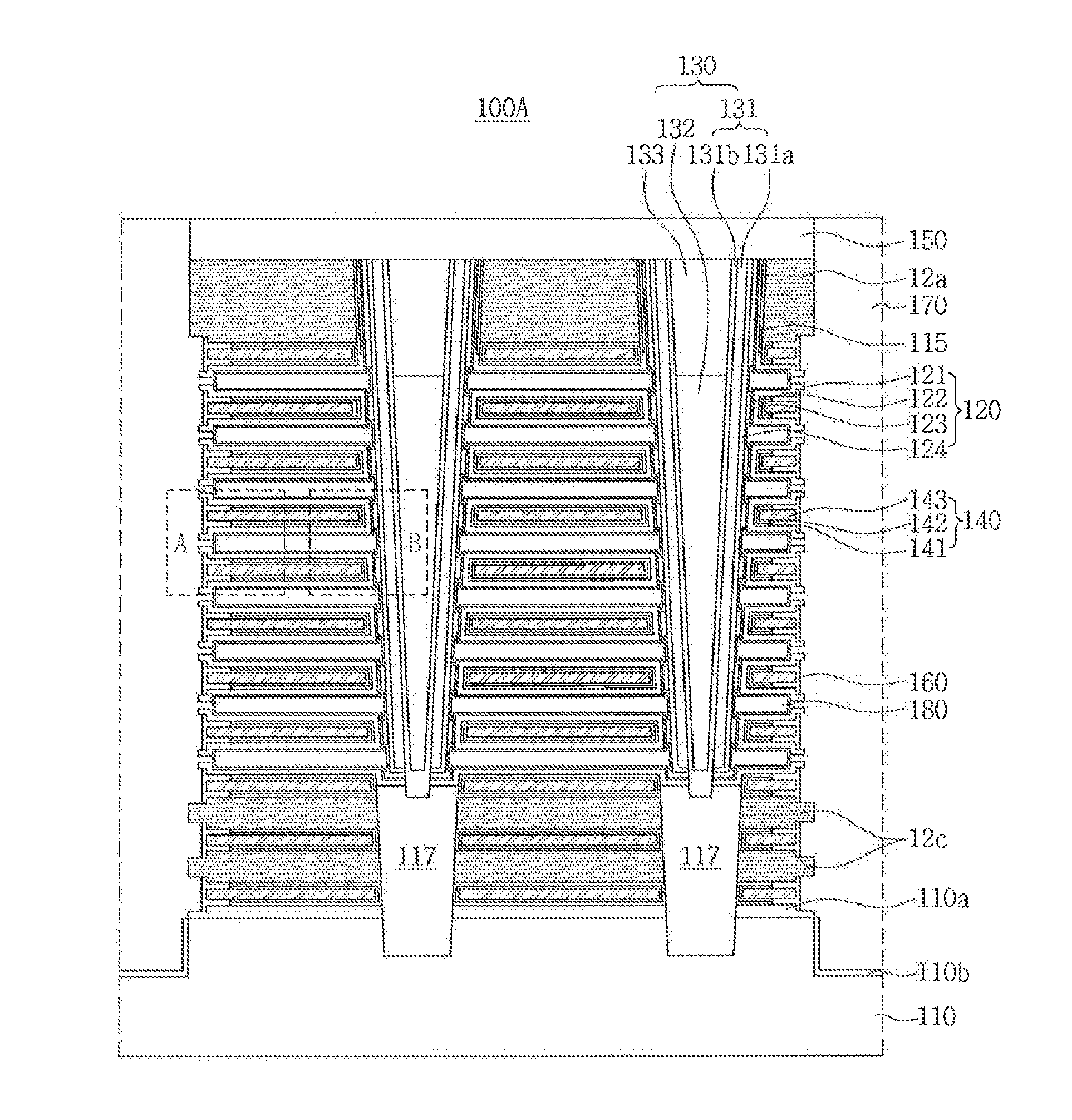
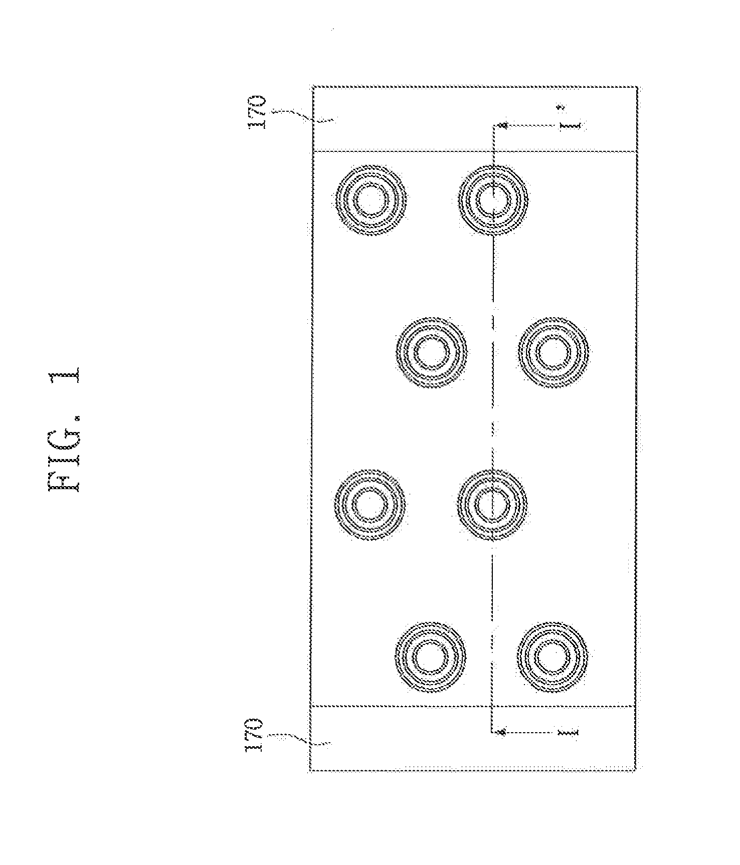
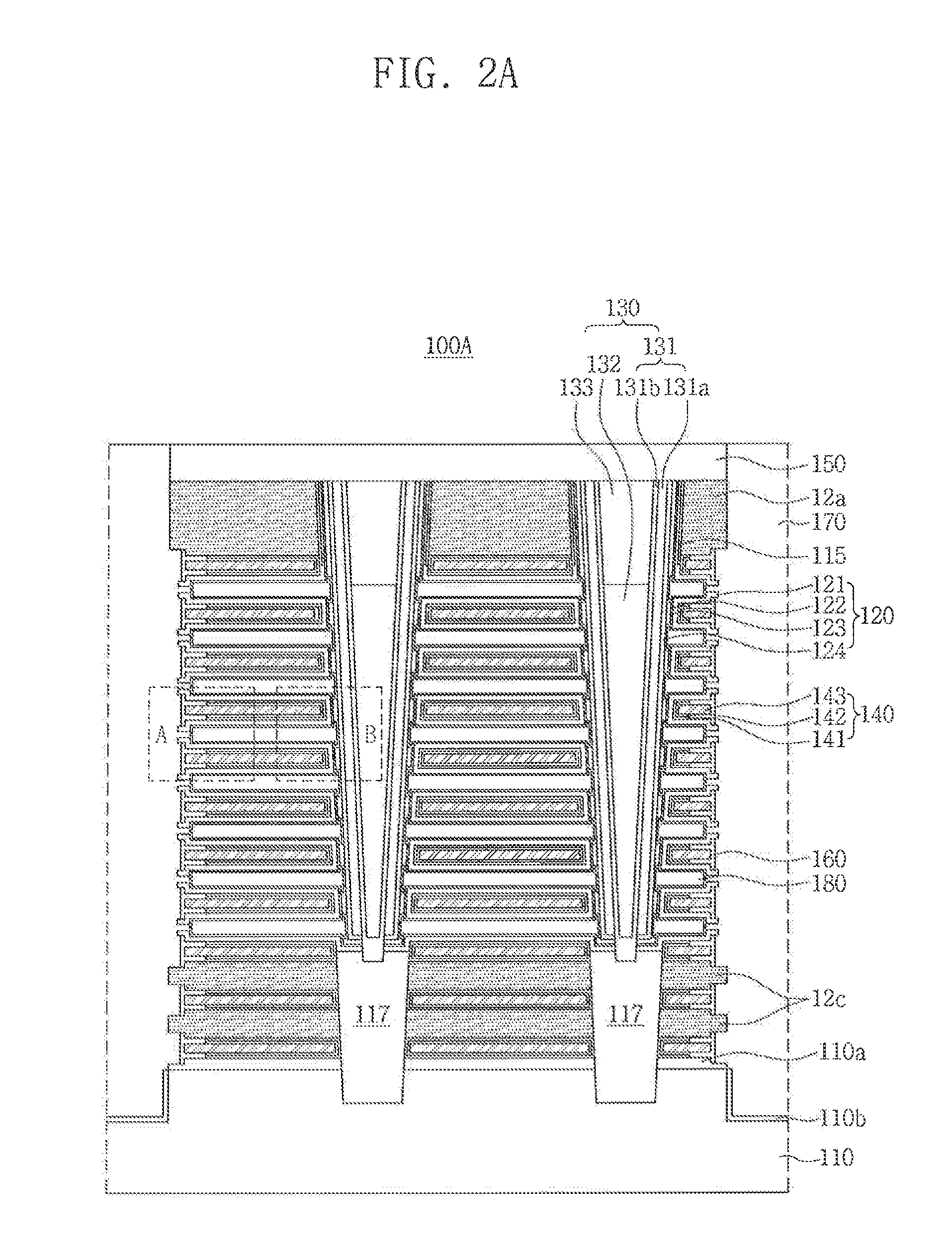
[0016]FIGS. 1 and 2A show top view and a cross-sectional view of a semiconductor device in accordance with ...


PUM


Abstract

A semiconductor device is provided. Word lines are formed on a substrate. An air gap is interposed between two adjacent word lines. A channel structure penetrates through the word lines and the air gap. A memory cell is interposed between each word line and the channel structure. The memory cell includes a blocking pattern, a charge trap pattern and a tunneling insulating pattern. The blocking pattern conformally covers a top surface, a bottom surface, and a first side surface of each word line. The first side surface is adjacent to the channel structure. The charge trap pattern is interposed only between the first side surface and the channel structure.

Description

CROSS-REFERENCE TO RELATED APPLICATION[0001]This application claims priority under 35 U.S.C. §119 to Korean Patent Application No. 10-2014-0078205, filed on Jun. 25, 2014 in the Korean Intellectual Property Office, the disclosure of which is incorporated by reference herein in its entirety.TECHNICAL FIELD[0002]The present inventive concept relates to a semiconductor device having a vertical channel and an air gap.DISCUSSION OF RELATED ART[0003]Various methods of vertically forming a plurality of memory cells on a substrate are being studied to increase performance and integration density. As the number of stacked cells increases, the thickness of the stacked cells increases to the extent that an etching process is difficult. As the thickness of the stacked cells reduces, an operational speed thereof may be lowered due to coupling capacitance between word lines to the extent that a read operation error may occur.SUMMARY[0004]According to an exemplary embodiment of the present inventi...

Claims


Application Information

Patent Timeline
IPC IPC(8): H01L27/115H01L23/528H01L23/532H01L29/792
CPCH01L27/11582H01L27/11565H01L27/1157H10B43/10H10B43/35H10B43/27H01L29/78696
Inventor KANAMORI, KOHJIKIM, CHUNG-JINPARK, YOUNG-WOOLEE, JAE-GOOLEE, JAE-DUKCHOI, MOO-RYM
Owner SAMSUNG ELECTRONICS CO LTD
Learn More