

System and method for reception mode switching in dual-carrier wireless backhaul networks
a dual-carrier fixed wireless and backhaul network technology, applied in data switching networks, frequency-division multiplexes, instruments, etc., can solve the problems of interference cancellation or rejection, high cost of spectrum, and the performance of the system is far from an interference-free performance upper bound in capacity and reliability, etc., to achieve the elimination or mitigation of the disadvantages of the known system and method
- Summary
- Abstract
- Description
- Claims
- Application Information
AI Technical Summary
Benefits of technology
Problems solved by technology
Method used
Image

Examples
Embodiment Construction
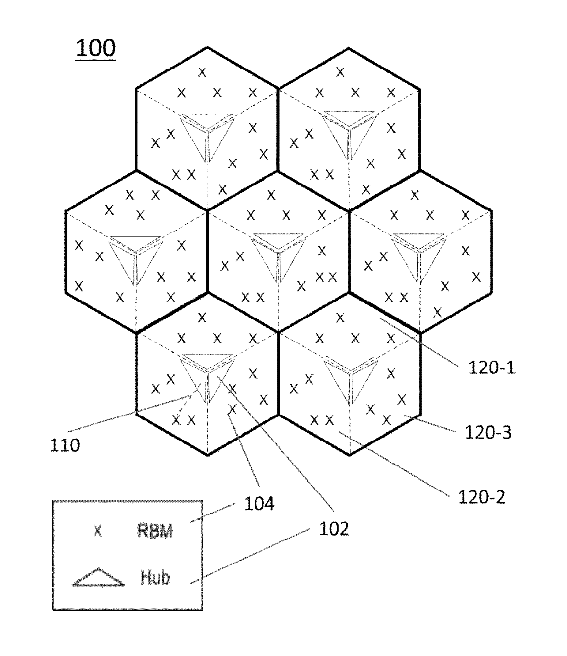
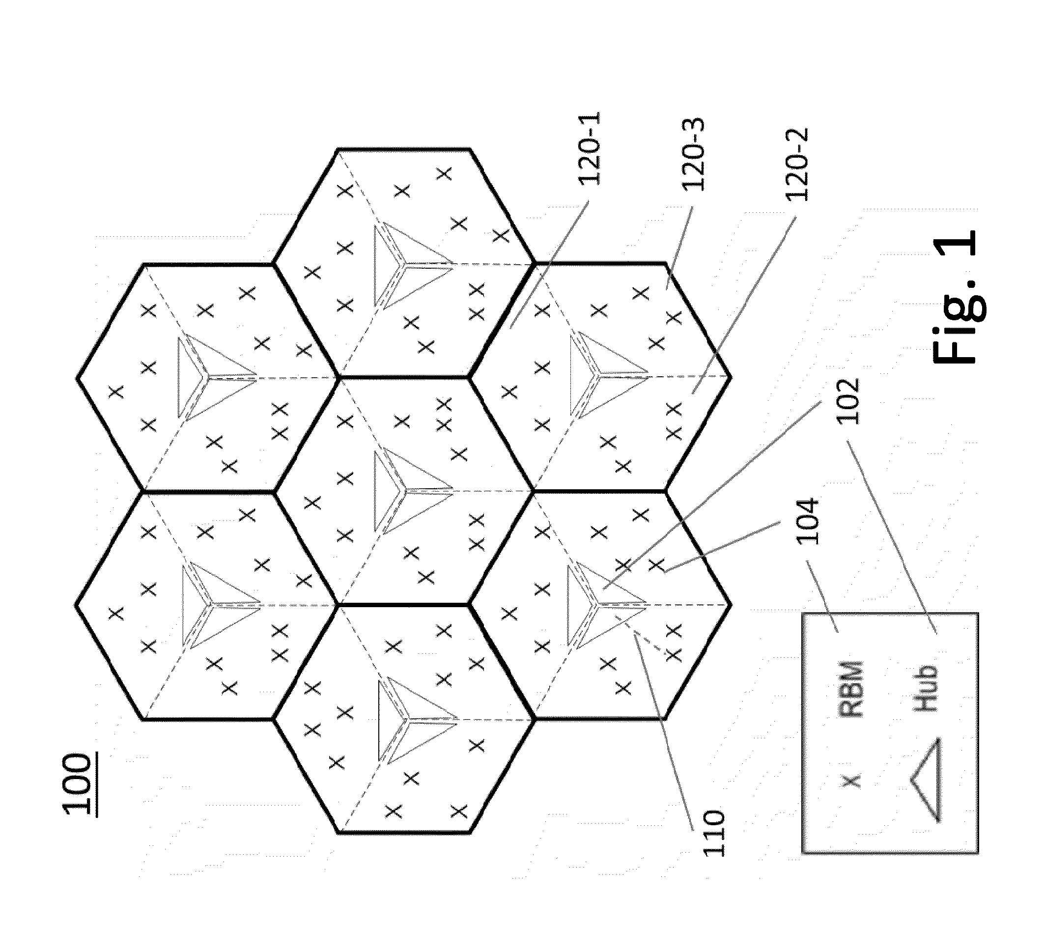
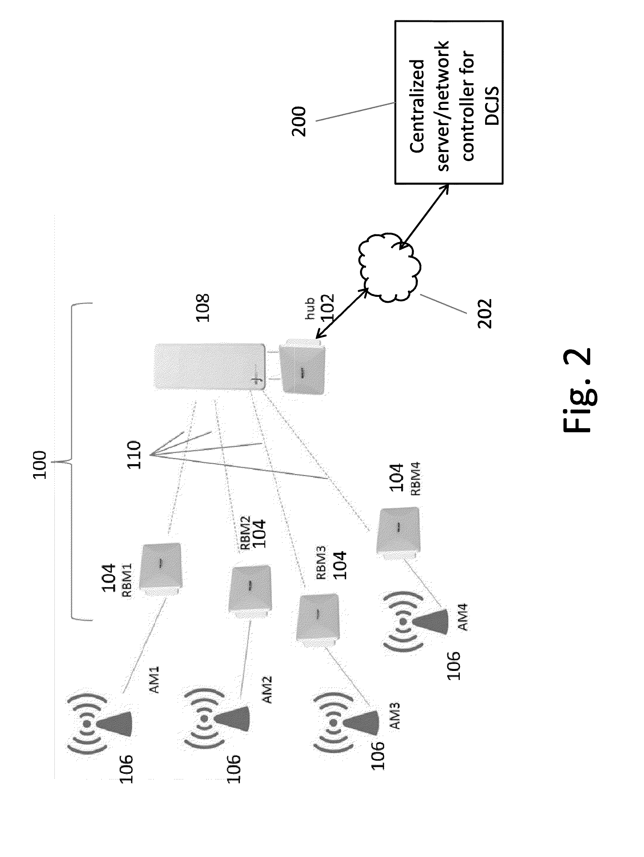
[0059]A system and method for reception mode selection in a dual carrier wireless backhaul network will be described, by way of example, with reference to a NLOS wireless backhaul network 100 as illustrated schematically in FIG. 1, which represents schematically the topology of a system comprising a point-to-multipoint wireless backhaul network, comprising a plurality of fixed nodes. The nodes comprise a plurality of Hubs 102 and RBMs 104.
[0060]As an example only, the wireless backhaul network 100 shown in FIG. 1 comprises a plurality of seven sites or cells, each site comprising three Hub modules 102, with each Hub module serving a sector 120 comprising a cluster of a plurality of Remote Backhaul Modules (RBMs) 104. Thus, there are 21 sectors, each with a Hub module 102 serving a cluster of up to four RBMs. As shown, three Hubs modules 102, each with directional antenna, are co-located in each of the cell centers, with a cluster of RBMs mapped to each respective serving Hub, in eac...
PUM
 Abstract
Description
Claims
Application Information