
Method and system for network planning in fixed wireless backhaul networks

a fixed wireless backhaul and network planning technology, applied in the direction of wireless communication, electrical equipment, network topologies, etc., can solve the problems of not providing real-time performance, requiring significant data inputs, and slowness of commercially available rf planning tools, so as to eliminate or mitigate the disadvantages of known systems and methods

Active Publication Date: 2018-12-04
BLINQ NETWORKS
View PDF6 Cites 7 Cited by
  • Summary
  • Abstract
  • Description
  • Claims
  • Application Information

AI Technical Summary

Benefits of technology

[0010]The present invention seeks to eliminate, or at least mitigate, disadvantages of known systems and methods, or at least provide an alternative.
[0015]Thus beneficially network planning for backhaul networks can be done rapidly and effectively with limited input data, even in the absence high resolution digital maps or building polygons, by modelling a proposed wireless backhaul network using channel models having a highest correlation with available environmental parameters, e.g. information from elevation maps (e.g. elevation relative to sea level), average building heights, street widths and layout.
[0033]joint hub pointing; hub deployment (hub dimensioning=number of hubs); hub association; RBM pointing; comprising sweeping all parameters (feature options) to maximize the utility function;
[0042]Advantageously, methods and systems according to exemplary embodiments of the invention provide for fast backhaul network planning, even when user inputs are limited, e.g. in the absence of high resolution digital maps, building polygons, et al.

Problems solved by technology

Commercially available RF planning tools are generally slow in nature, require significant data inputs, and do not provide real-time performance results.

Method used


Image

  • Method and system for network planning in fixed wireless backhaul networks
  • Method and system for network planning in fixed wireless backhaul networks
  • Method and system for network planning in fixed wireless backhaul networks

Examples


Embodiment Construction

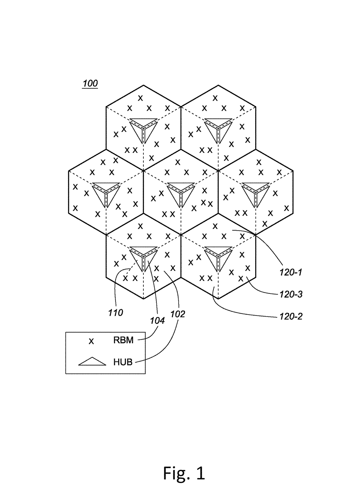
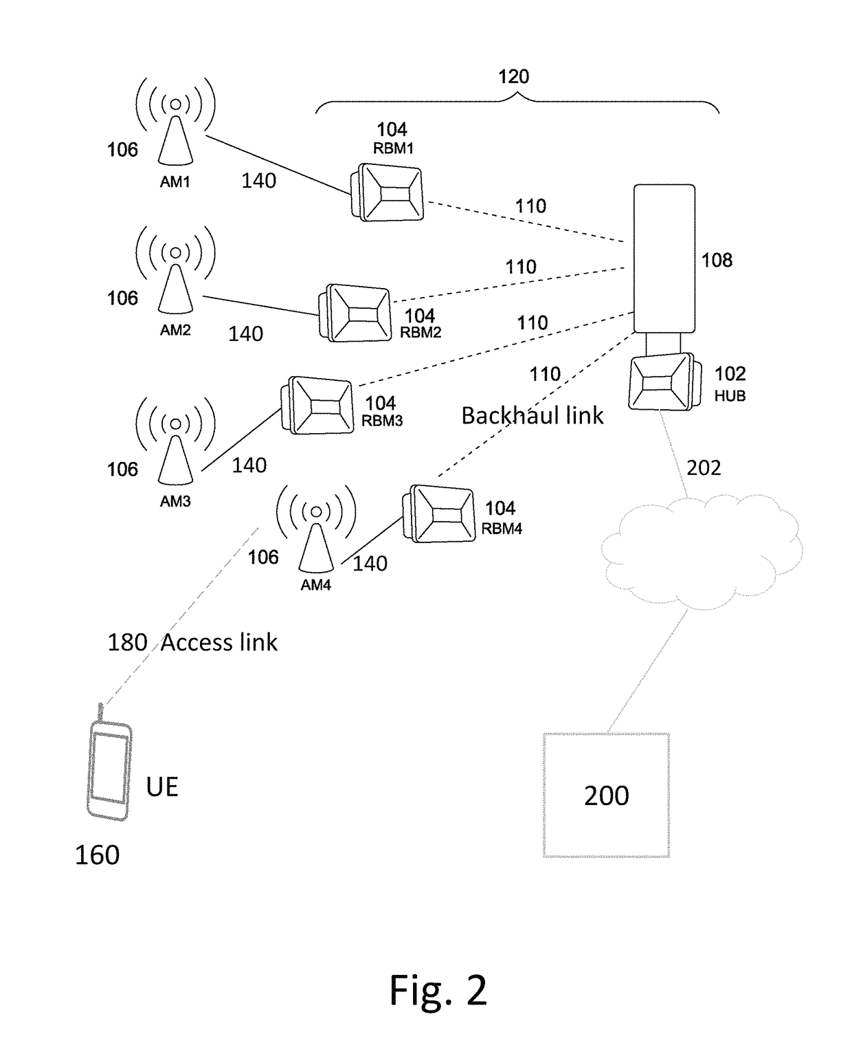
[0075]A system and method for network planning a wireless backhaul network according to an embodiment of the present invention will be described, by way of example, with reference to a NLOS wireless backhaul network 100 as illustrated schematically in FIG. 1, which represents schematically the topology of a system comprising a point-to-point wireless backhaul network, comprising a plurality of fixed nodes. The nodes comprise a plurality of hubs 102 and RBMs 104.

[0076]As an example only, the wireless backhaul network 100 shown in FIG. 1 comprises a plurality of seven sites or cells, each site comprising three hub modules 102, with each hub module serving a sector 120 comprising a cluster of a plurality of Remote Backhaul Modules (RBMs) 104. Thus, there are 21 sectors, each with a hub module 102, serving a cluster of up to four RBMs. As shown, three hubs modules 102, each with directional antenna, are co-located in each of the cell centers, with a cluster of RBMs mapped to each respec...


PUM


Abstract

Systems and methods are disclosed for networking planning for fixed backhaul networks comprising a plurality of hubs, each serving one or more RBMs. The method comprises one or more of terrain pathloss (PL) and antenna gain prediction; network design comprising site association, hub dimensioning and pointing; and optimization of small cell (SC) deployment. PL prediction is based on correlation of user input parameters with reference use cases for channel models for each of downtown, urban, and suburban deployment scenarios. Rapid and effective network planning is achieved with limited input data, even in the absence of high resolution digital maps or building polygons, by selecting the channel model having a highest correlation with available environmental parameters. Optimization of network topology design, system design, and SC deployment, with both access link and backhaul link evaluation, is based on optimization of a sum-utility function across all links for feasible SC site locations.

Description

CROSS-REFERENCE TO RELATED APPLICATIONS[0001]This application is related to U.S. patent application Ser. No. 14 / 643,022, entitled “System And Method of Signalling For Point-To-Multi-Point (PtMP) Transmission In Fixed Wireless Backhaul Networks” filed Mar. 10, 2015; U.S. patent application Ser. No. 14 / 215,798, entitled “System and Method for Joint Scheduling in Dual-Carrier Wireless Backhaul Networks”, filed Jun. 14, 2014; U.S. patent application Ser. No. 14 / 255,068, entitled “System and Method for Coordinating Hub Beam Selection in Fixed Wireless Backhaul Networks”, filed Apr. 17, 2014; U.S. patent application Ser. No. 14 / 073,459, entitled “Method and System for Performance Management in Wireless Backhaul Networks via Power Control”, filed Nov. 6, 2013, claiming priority from U.S. Provisional patent application No. 61 / 723,494, entitled “Method and Apparatus for Inter-Cluster Power Management”, filed on Nov. 7, 2012; U.S. patent application Ser. No. 14 / 462,859, entitled “System and M...

Claims


Application Information

Patent Timeline
Patent Type & Authority Patents(United States)
IPC IPC(8): H04W16/18H04W84/04
CPCH04W16/18H04W84/045
Inventor CHENG, HO TINGNIYOMSATAYA, TERASANSELEA, RADU BOGDAN
Owner BLINQ NETWORKS
Learn More