
System and method for downlink power optimization in a partitioned wireless backhaul network with out-of-neighborhood utility evaluation

a wireless backhaul network and utility evaluation technology, applied in the field of telecommunications service network technology, can solve the problems of higher hub transmit power, computational complexity of power optimization across the entire network, and system performance tend to degrade, so as to eliminate or mitigate the disadvantages of known systems and methods

Active Publication Date: 2015-09-22
BLINQ NETWORKS
View PDF13 Cites 0 Cited by
  • Summary
  • Abstract
  • Description
  • Claims
  • Application Information

AI Technical Summary

Benefits of technology

The invention aims to improve the performance of known systems and methods by taking into account both in-neighborhood and out-of-neighborhood utilities in downlink power optimization. This approach helps to reduce performance degradation in partitioned networks and provide better overall performance.

Problems solved by technology

However, in practice, power optimization across the entire network can be computationally complex.
However, system performance tends to degrade if each partition or neighborhood tries to maximize its sum utility by optimizing its own power levels independently of other partitions or neighborhoods.
Employing the same power optimization method independently in each neighborhood will result in higher hub transmit power and hence, poorer overall system performance.
However, this methodology generally requires a joint power control and network partitioning optimization, which can be computationally expensive.
However, this approach is not scalable.

Method used


Image

  • System and method for downlink power optimization in a partitioned wireless backhaul network with out-of-neighborhood utility evaluation
  • System and method for downlink power optimization in a partitioned wireless backhaul network with out-of-neighborhood utility evaluation
  • System and method for downlink power optimization in a partitioned wireless backhaul network with out-of-neighborhood utility evaluation

Examples


Embodiment Construction

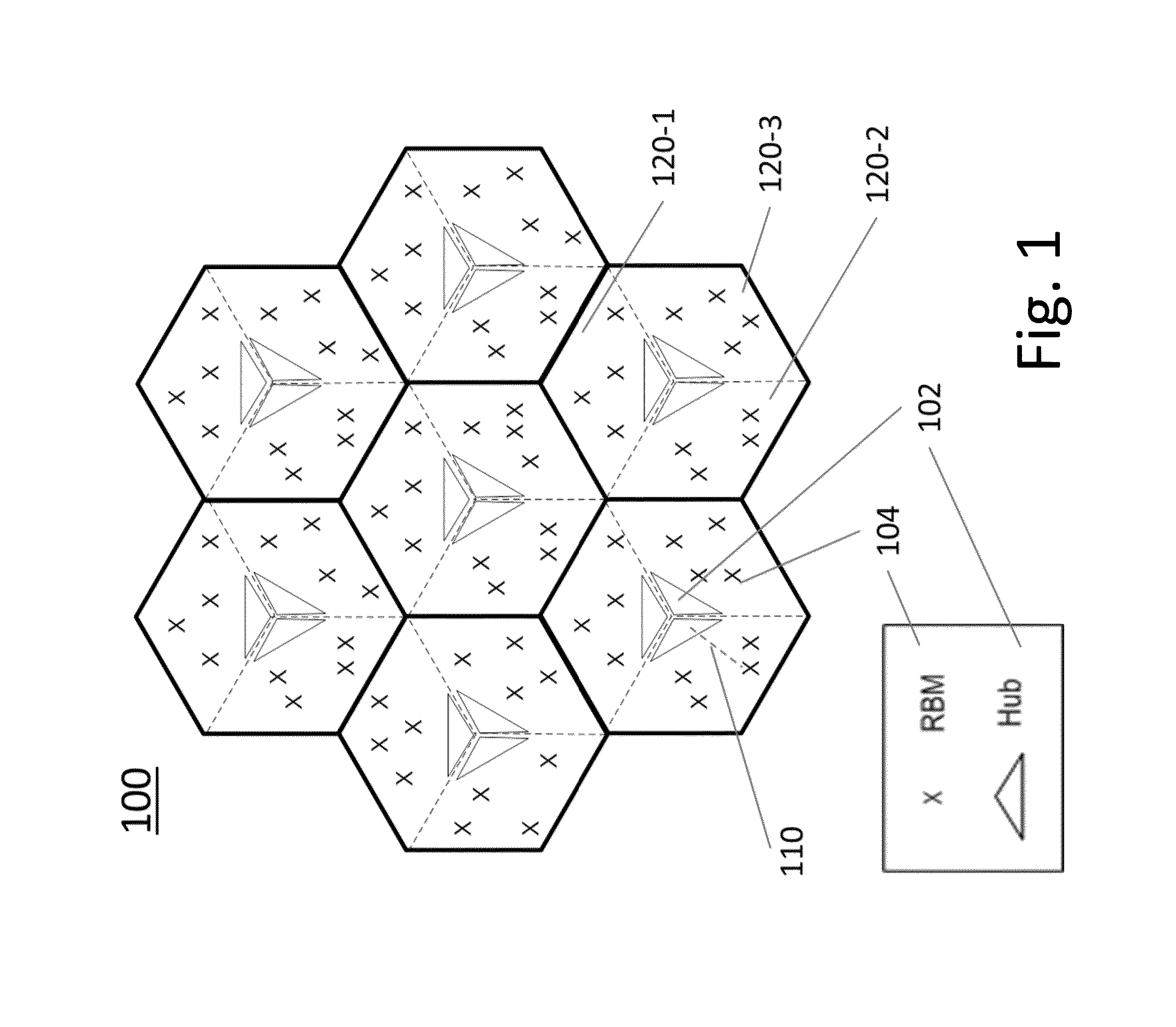
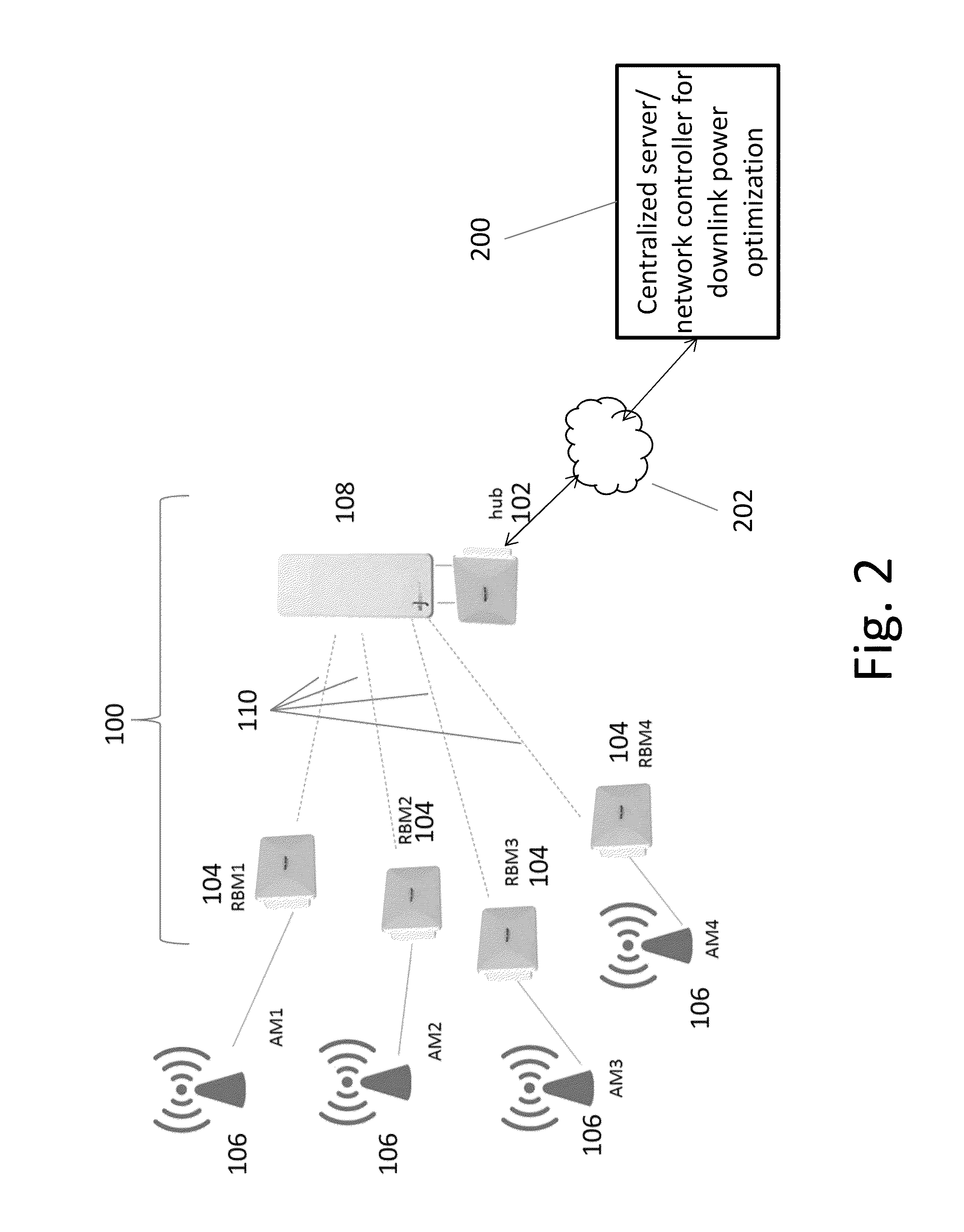
[0047]A system and method for downlink power optimization in a partitioned wireless backhaul network with out-of-neighborhood utility evaluation will be described, by way of example, with reference to a NLOS wireless backhaul network 100 as illustrated schematically in FIG. 1, which represents schematically the topology of a system comprising a point-to-multipoint wireless backhaul network, comprising a plurality of fixed nodes. The nodes comprise a plurality of hubs 102 and RBMs 104.

[0048]As an example only, the wireless backhaul network 100 shown in FIG. 1 comprises a plurality of seven sites or cells, each site comprising three hub modules 102, with each hub module serving a sector 120 comprising a cluster of a plurality of Remote Backhaul Modules (RBMs) 104. Thus, there are 21 sectors, each with a hub module 102, serving a cluster of up to four RBMs. As shown, three hubs modules 102, each with directional antenna, are co-located in each of the cell centers, with a cluster of RBM...


PUM


Abstract

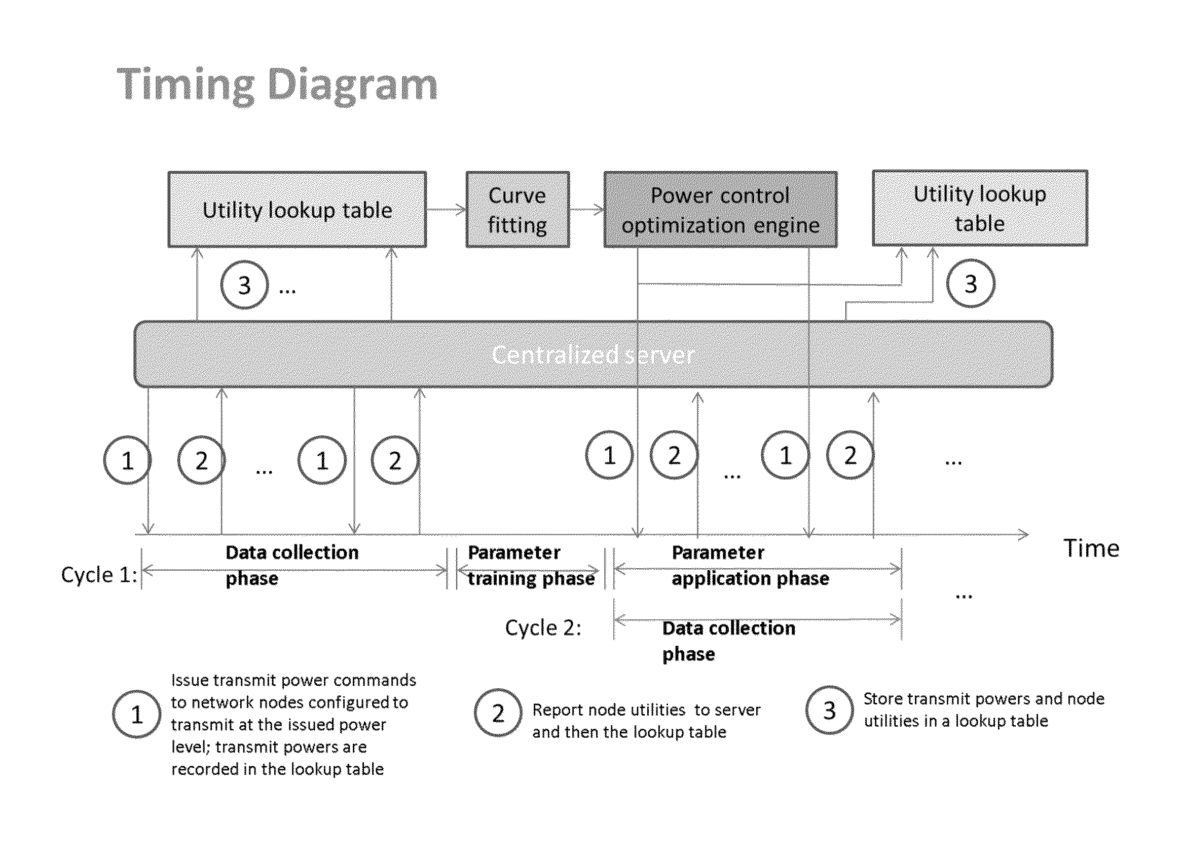
A system and method for downlink power optimization in a partitioned wireless backhaul network with out-of-neighborhood utility evaluation is disclosed. The method comprises performing initial downlink power optimization for each neighborhood independently, considering only in-neighborhood utilities, by obtaining the transmit powers of all hubs and a utility performance of all served remote backhaul modules (RBMs) in the neighborhood. Power optimization data for each neighborhood are then reported to a central processing unit for storage. Thereafter, for each neighborhood, an out-of-neighborhood utility evaluation is performed by the centralized processing unit, based on reported power optimization data from other neighborhoods, for example, by obtaining delta out-of-neighborhood sum utilities for each hub as a function of hub transmit power, by curve fitting of reported data. Power optimization for each neighborhood is then performed by optimizing both in-neighborhood sum utilities and out-of-neighborhood sum utilities, and hub transmit powers are updated accordingly.

Description

CROSS-REFERENCE TO RELATED APPLICATIONS[0001]This application claims priority from U.S. Provisional patent application No. 61 / 868,787, filed Aug. 22, 2013, entitled “System and Method for Downlink Power Optimization with Out-of-neighborhood Utility Evaluation in Partitioned Wireless Backhaul Networks”, which is incorporated herein by reference in its entirety.[0002]This application is related to International Patent Application No. PCT / CA2011 / 001020 and to U.S. patent application Ser. No. 13 / 230,368, both of which were filed Sep. 12, 2011, entitled “System and Method for Co-Channel Interference Measurement And Managed Adaptive Resource Allocation for Wireless Backhaul”, claiming priority from U.S. Provisional patent application No. 61 / 382,217, filed Sep. 13, 2010; this application is also related to U.S. patent application Ser. No. 14 / 073,459, entitled “Method and System for Performance Management in Wireless Backhaul Networks via Power Control”, filed Nov. 6, 2013, claiming priorit...

Claims


Application Information

Patent Timeline
Patent Type & Authority Patents(United States)
IPC IPC(8): H04W40/00H04W52/50H04W52/14H04W52/24H04W16/10H04W52/34H04W52/26H04W52/38H04W24/02H04W72/54
CPCH04W52/146H04W16/10H04W52/143H04W52/241H04W52/242H04W52/262H04W52/34H04W52/386H04W52/50H04W24/02
Inventor CHENG, HO TINGTANG, TAIWENNIYOMSATAYA, TERASANMICHNEA, SORIN ALEXANDRUSELEA, RADU BOGDAN
Owner BLINQ NETWORKS
Learn More