Mechanical seal device

a mechanical seal and sealing fluid technology, applied in the direction of engine seals, mechanical apparatus, engine components, etc., can solve the problems difficulty in properly maintaining a clearance between sliding surfaces, and prone to damage, so as to achieve the effect of reducing the structure of o-rings, springs and the like contacting with sealed fluid, avoiding leakage, and avoiding leakag

Inactive Publication Date: 2016-01-07
EAGLEBURGMANN JAPAN +1
View PDF9 Cites 16 Cited by
  • Summary
  • Abstract
  • Description
  • Claims
  • Application Information

AI Technical Summary

Benefits of technology

[0017]Further, for the mechanical seal device of the present invention, the pressure of the sealed fluid is applied to the outer circumference of the bellows, and the bellows is able to exhibit its sealing performance and also to apply a compressive force. Therefore, the structure of O-rings, springs and the like contacting with the sealed fluid can be reduced. Further, in the present invention, by smoothly moving the stationary seal ring in the axial direction, it enables to exhibit preferable sealing performance. Further, the bellows is extendable in the axial direction and also deformable in a radial direction, with the result that it enables the s

Problems solved by technology

However, in a conventional static pressure mechanical seal device, due to a pressure fluctuation inside of the machine, a balance between the pressure inside of the machine and the pressure of the purge gas is broken, with the result that it tended to be difficult to properly maintain a clearance between sliding surfaces.
For example, as the pressure inside of the machine is higher than the predetermined pressure, the clearance between the sliding surfaces is opened more than necessary, with the result that the sealed fluid might be leaked toward the outside of the machine.
Further, as the pressure inside of the machine is lower than the predetermined pressure, it causes contacts of sliding surfaces, with the result that the sliding surfaces tended to be damaged.
However, for the conventional mechanical seal device

Method used


Image

  • Mechanical seal device
  • Mechanical seal device
  • Mechanical seal device

Examples


first embodiment

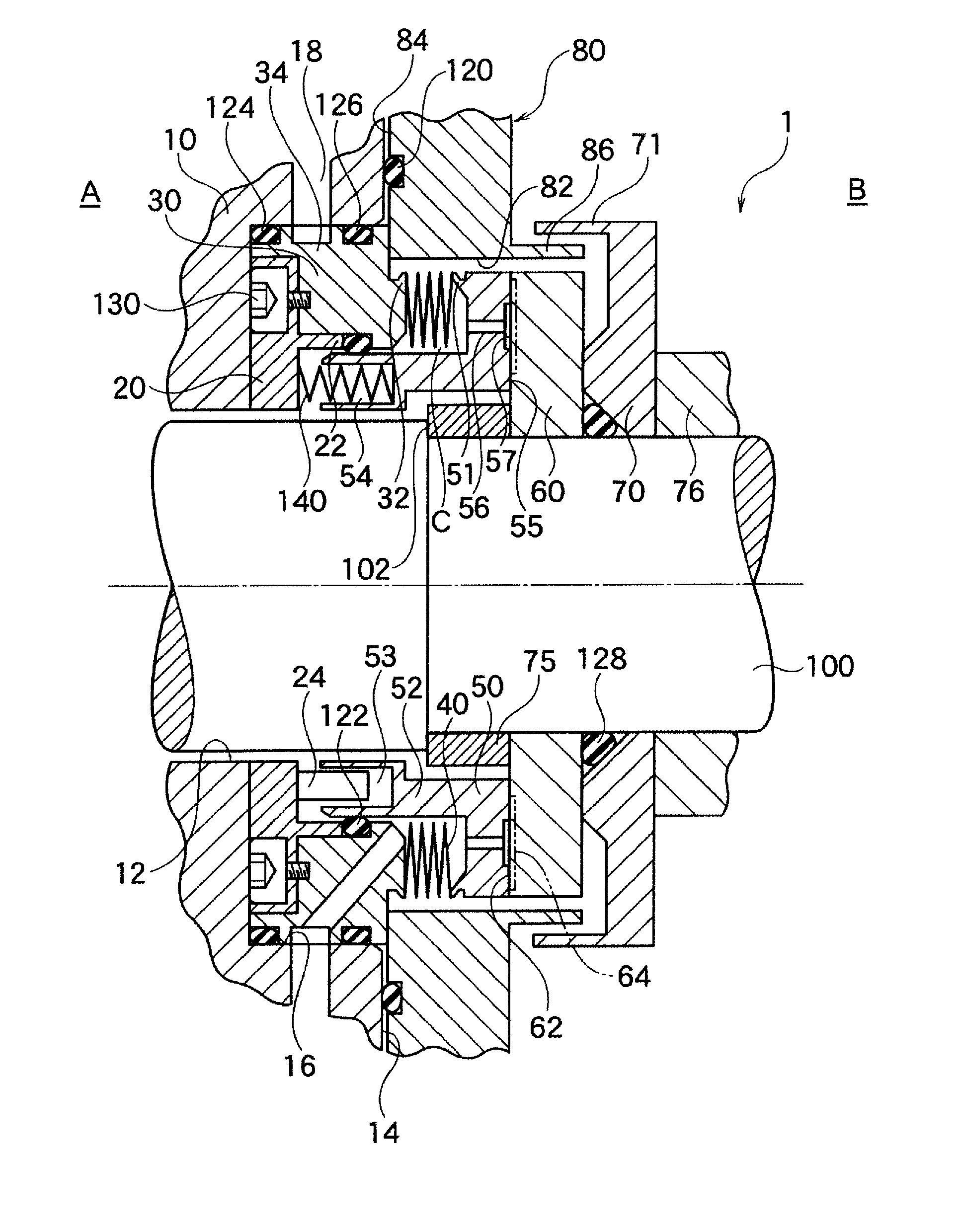
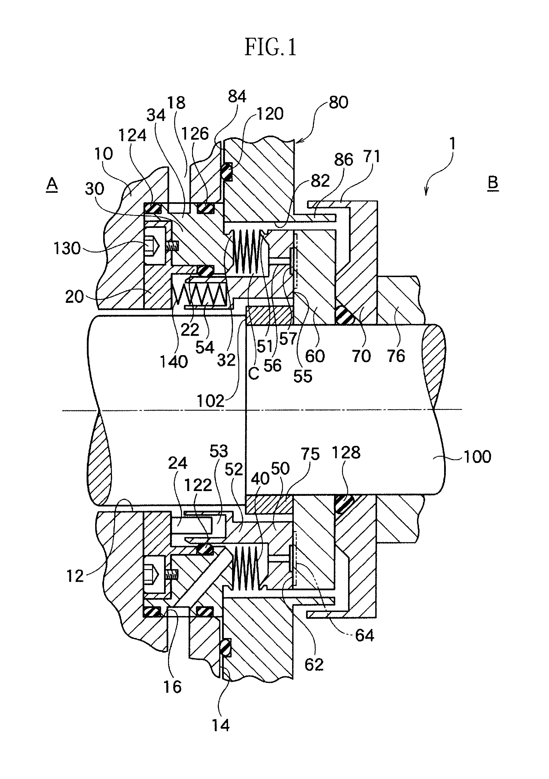
[0032]A mechanical seal device 1 according to the present embodiment is a seal device mounted on apparatuses such as stirring machines for general industrial use, blowers, compressors and the like. Particularly, it is used for purposes of manufacturing food products, medical products and chemical substances.

[0033]The mechanical seal device 1 has an inside type structure, in which the sealed fluid is arranged outside in a radial direction with respect to a sealing surface. The sealed fluid at a machine inside B is sealed by the seal device 1 arranged at a clearance formed between a rotary shaft 100 and a stuffing box 80. Further, in FIGS. 1 and 2, the left side in the axial direction is a machine outside A and the right side in the axial direction is the machine inside B.

[0034]A shaft hole 82 is formed through the stuffing box 80, and the rotary shaft 100 rotatably supported by bearings which is not expressed with a figure, extends through this shaft hole 82. At the inner side of the...

second embodiment

[0061]As illustrated in FIG. 5, a mechanical seal device 1a according to the present embodiment is an alternative of the mechanical seal device 1 of the first embodiment illustrated in FIGS. 1 to 4, and has the same structure and the same function effects with the first embodiment except for the followings. For the structure common to the first embodiment, similar marks are used in the figure and the explanations for the overlapped parts are omitted.

[0062]In this embodiment, inside of the static pressure fluid chamber C, a plurality of coil springs 140a serving as resilient members are intermittently arranged in a circumferential direction. In order to achieve the above structure, in this embodiment, a cylindrical protruding portion 26 extending toward the rotary seal ring 60 is integrally formed on a radially inner end of the adapter 20. At an outer circumference of tip end of the cylindrical protruding portion 26, a cylindrical portion 52a of the static seal ring 50 is movably mou...


PUM


Abstract

A mechanical seal device 1 comprises a seal case 30 attached to the device main body, a rotary seal ring 60 attached to the rotary shaft 100, a stationary seal ring 50 arranged in an axial direction opposing to the rotary seal ring 60, and a bellows 40 attached extendably in the axial direction between the stationary seal ring 50 and the seal case 30. A static pressure fluid supplying hole 56, supplying a static pressure fluid to a static pressure fluid chamber C arranged at an inner circumferential side of the bellows, is formed on the seal case 30. A communication hole, guiding the static pressure fluid of the static pressure fluid chamber C to sealing surfaces between the stationary seal ring 50 and the rotary seal ring 60 is formed on the stationary seal ring 50. The sealed fluid is arranged at an outer circumferential side of the bellows 40.

Description

TECHNICAL FIELD[0001]The present invention relates to a mechanical seal device.BACKGROUND ART[0002]Conventionally, as a mechanical seal device, a static pressure mechanical seal device preventing a fluid sealed inside a machine from leaking toward the outside of the machine is known. For such static pressure mechanical seal device, by supplying higher purge gas on a seal surface compared to the sealed fluid, the purge gas is leaked toward the inside and the outside of the machine, with the result that the seal fluid is prevented from leaking toward the outside of the machine.[0003]However, in a conventional static pressure mechanical seal device, due to a pressure fluctuation inside of the machine, a balance between the pressure inside of the machine and the pressure of the purge gas is broken, with the result that it tended to be difficult to properly maintain a clearance between sliding surfaces. For example, as the pressure inside of the machine is higher than the predetermined p...

Claims


Application Information

Patent Timeline
IPC IPC(8): F16J15/36F16J15/34
CPCF16J15/36F16J15/3408F16J15/3436F16J15/342F16J15/363F16J15/3448F16J15/3416
Inventor TAKAHASHI, HIDEKAZUMURAKI, RYOJI
Owner EAGLEBURGMANN JAPAN
Why Eureka
Try Eureka