
Ball tracker camera

a technology of ball tracker and camera, which is applied in the field of camera control, can solve the problems of camerapersons losing track of balls (or other types of equipment), gaps in the action of events, and unhappy or dissatisfied,

Active Publication Date: 2016-01-14
PROSPORTS TECH
View PDF0 Cites 15 Cited by
  • Summary
  • Abstract
  • Description
  • Claims
  • Application Information

AI Technical Summary

Benefits of technology

The present invention is a system and method for tracking a ball in real-time using wireless signals. The system includes an identification processor coupled to the ball and at least three triangulation antennas distributed at different locations within an event venue. The signals received by the antennas are used to determine the location of the ball in real-time. A controller then adjusts a gimbal to point the camera at the determined location of the ball. The technical effect of the invention is to enable accurate and efficient ball tracking in various sports activities.

Problems solved by technology

There may be instances where a cameraperson may lose track of the ball (or other type of equipment).
In such instances, the camera may be unable to capture the current state of the ball, resulting in gaps in the action of the event.
Audiences—both those viewing remotely and those present in-person, but may be relying on the camera for close-ups—may then become unhappy or dissatisfied as a result of being unable to view the entirety of the event.

Method used


Image

  • Ball tracker camera
  • Ball tracker camera
  • Ball tracker camera

Examples


Embodiment Construction

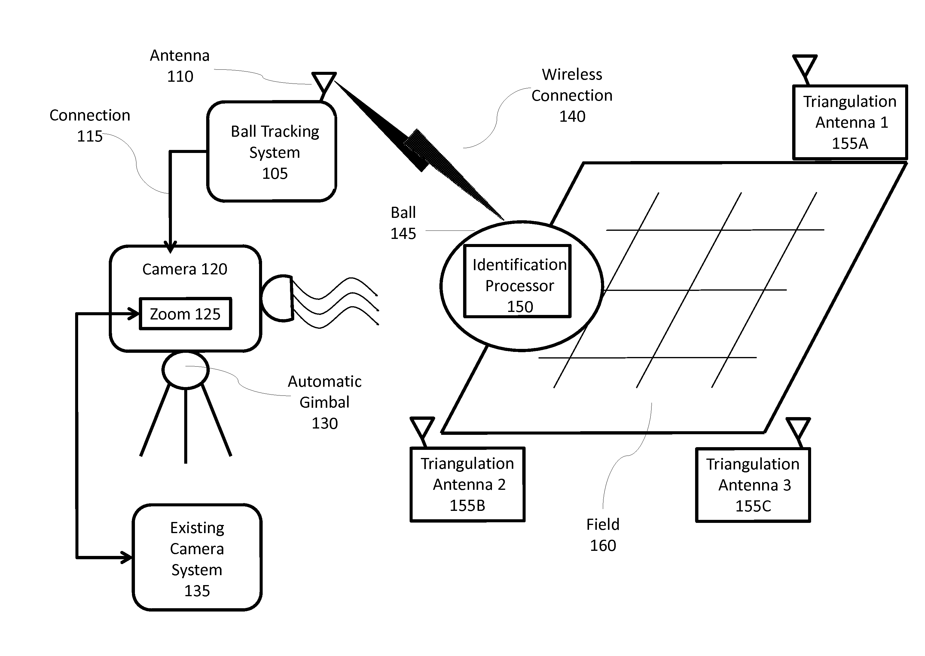
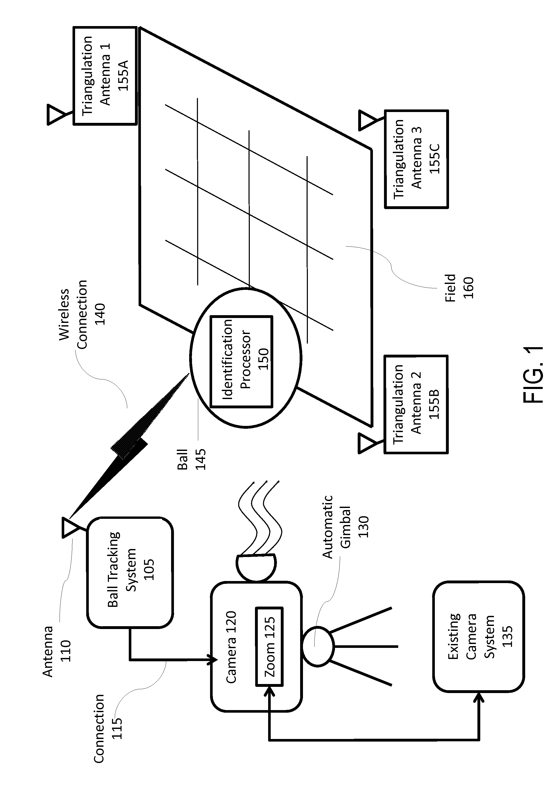
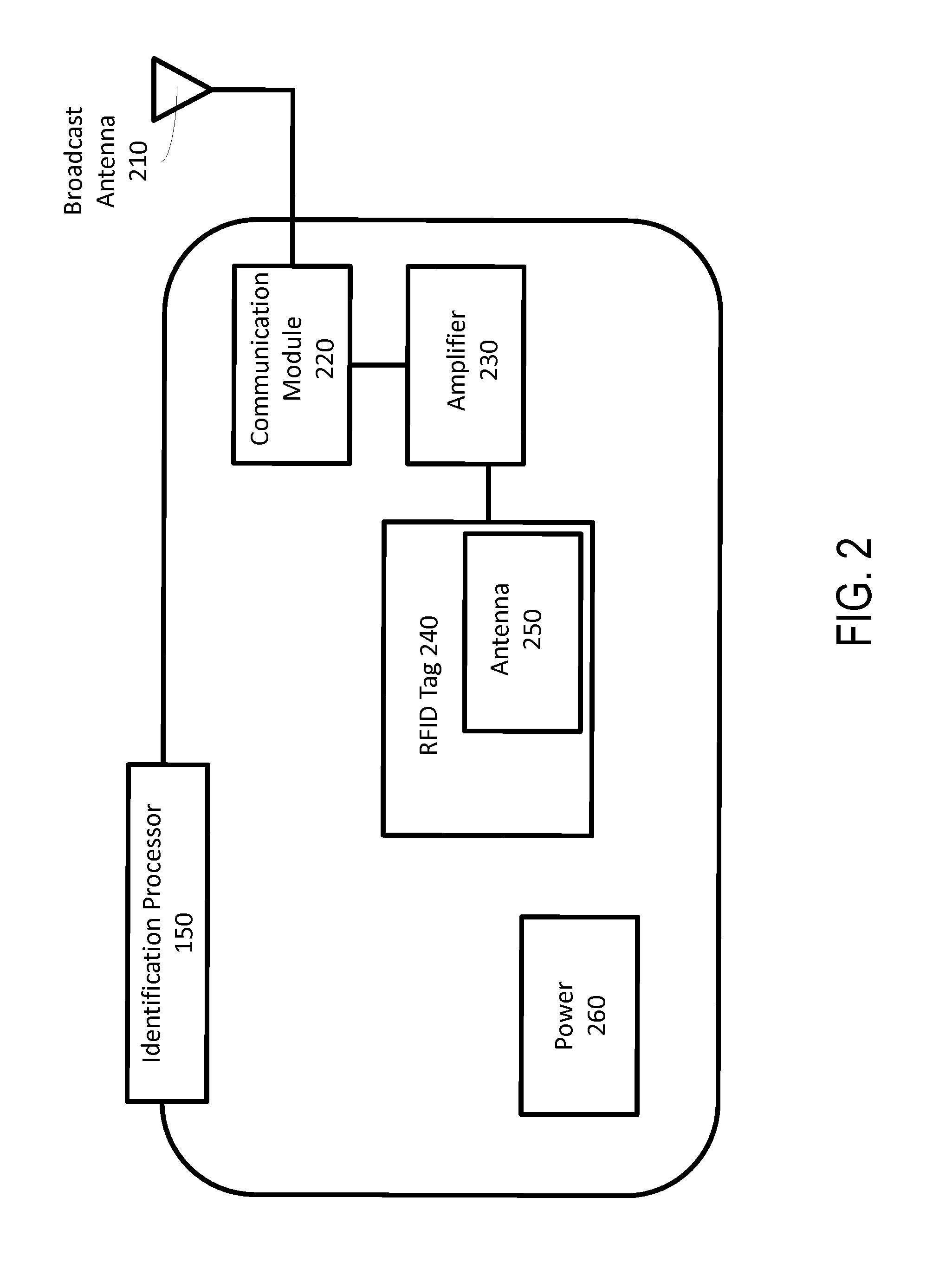
[0015]Embodiments of the present invention include systems and methods for ball tracking. An identification processor may be coupled to a ball and may generate wireless signals as the ball is moving. At least three triangulation antennas may be distributed at different locations within an event venue. Such triangulation antennas may receive the wireless signals from the identification processor in real-time. Such signals may be used to determine a real-time location of the ball within the event venue. A controller may then adjust a gimbal to point the camera at the determined real-time location of the ball.

[0016]FIG. 1 illustrates an exemplary environment in which a system for ball tracking may be implemented. As illustrated, the environment may include a ball tracking system 105 having an antenna 110 and a connection 115 to a camera 120 (with ability to zoom 125) on a gimbal 130. Such camera 120 may be part of an existing camera system 135. In addition, ball tracking system 105 may...


PUM


Abstract

Systems and methods for ball tracking are provided. An identification processor may be coupled to a ball and may generate wireless signals as the ball is moving. At least three triangulation antennas may be distributed at different locations within an event venue. Such triangulation antennas may receive the wireless signals from the identification processor in real-time. Such signals may be used to determine a real-time location of the ball within the event venue. A controller may then adjust a gimbal to point the camera at the determined real-time location of the ball.

Description

CROSS-REFERENCE TO RELATED APPLICATIONS[0001]The present patent application claims the priority benefit of U.S. provisional patent application 62 / 023,400 filed Jul. 11, 2014 and titled “NFL-0007 Ball Tracker Camera,” the disclosure of which is incorporated by reference herein.BACKGROUND OF THE INVENTION[0002]1. Field of the Invention[0003]The present invention generally relates to camera control. More specifically, the present invention relates to ball tracker camera control.[0004]2. Description of the Related Art[0005]Many events may be filmed for live (e.g., real-time) or recorded broadcast. Such events may include a variety of athletic and sporting events involving such equipment as balls, bats, pucks, etc. As the outcome of such athletic and sporting events depends on actions involving such equipment (e.g., a football), a camera (or multiple cameras) may often follow the ball as it is moving during the course of the event. Each such camera is generally controlled by a camerapers...

Claims


Application Information

Patent Timeline
Patent Type & Authority Applications(United States)
IPC IPC(8): A63B24/00G06T7/20H04N5/232
CPCA63B24/0021G06T7/204G06T7/2093G06T2207/30221A63B2024/0034G06T2207/30224H04N5/232G01S5/02G01S5/0226G01S2205/08H04N23/69H04N23/695
Inventor CRONIN, JOHNREASNER, NICK
Owner PROSPORTS TECH
Learn More