AI technical title is built by Patsnap AI team. It summarizes the technical point description of the patent document.
a fastener and joinery technology, applied in the field of panel systems, can solve the problems of gap deflecting away from the building at the seam section, irregular seam section between two adjacent panels, etc., and achieve the effect of less apparent seams and a smoke-free seam section
Inactive Publication Date: 2016-01-21
ROYAL GROUP
View PDF15 Cites 2 Cited by
Summary
Abstract
Description
Claims
Application Information
AI Technical Summary
This helps you quickly interpret patents by identifying the three key elements:
Problems solved by technology
Method used
Benefits of technology
Benefits of technology
[0010]In view of the foregoing, it is a feature of the embodiments described herein to provide a system of panels that provides an improved end-to-end seam section with the outer surfaces of the joined panels providing a generally planar surface. In various embodiments, adjacent panels in a siding system may overlap and interlock at a seam section in a secure fashion. Once interlocked, the siding panels may expand and contract without causing a bulge or gap at the seam section. One benefit of siding panel assembly may be that the expansion and contraction associated with the individual siding panels is transferred to the ends of the assembly, rather than the end of each individual siding panel. Another benefit of the siding panel assembly of the embodiments is that it allows for a smoother seam between individual panels, so that it is less apparent from all viewing angles, unlike vinyl siding where the pieces are overlapped, to allow for expansion and contraction.
Problems solved by technology
This expansion and contraction may cause irregularities in the seam section between two adjacent panels.
For example, if adjacent abutting panels expand, the ends of the adjacent panels may expand toward each other, causing them to deflect away from the building at the seam section.
If adjacent abutting panels contract, the ends of the panels may draw away from each other, resulting in a gap at the seam section.
The gapping created by expansion or contraction of the siding panels may leave openings that can be unsightly, and leave the siding and building surface susceptible to damage from the elements.
However, the overlapping region leaves an undesirable visible seam.
In addition, the gap between the two overlapping sections allows water, air, and insects to pass which may cause damage to the siding panels or the underlying building surface.
Furthermore, where the overlapping region is unfastened, the ends of the siding panels can separate, further exacerbating these issues.
However, the use of separate connector pieces complicates the installation and assembly of the siding panels.
Method used
Image
Click on the blue label to locate the original text in one second.
Reading with bidirectional positioning of images and text.
Examples
Embodiment Construction
[0025]The following description is intended to convey a thorough understanding of the embodiments by providing a number of specific embodiments and details involving a siding panel assembly. It is understood, however, that the invention is not limited to these specific embodiments and details, which are exemplary only. It is further understood that one possessing ordinary skill in the art, in light of known devices, systems and methods, would appreciate the use of the invention for its intended purposes and benefits in any number of alternative embodiments.
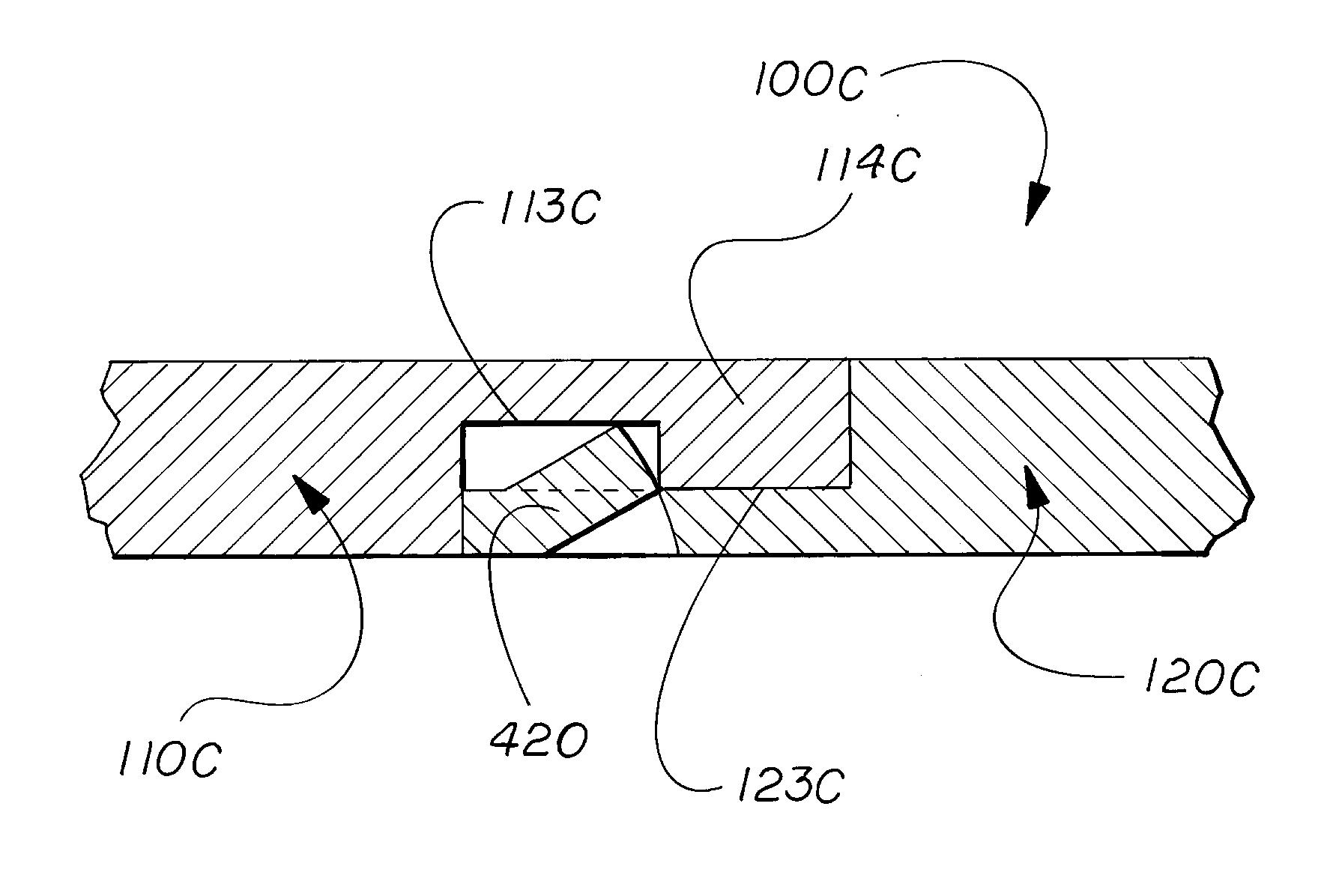
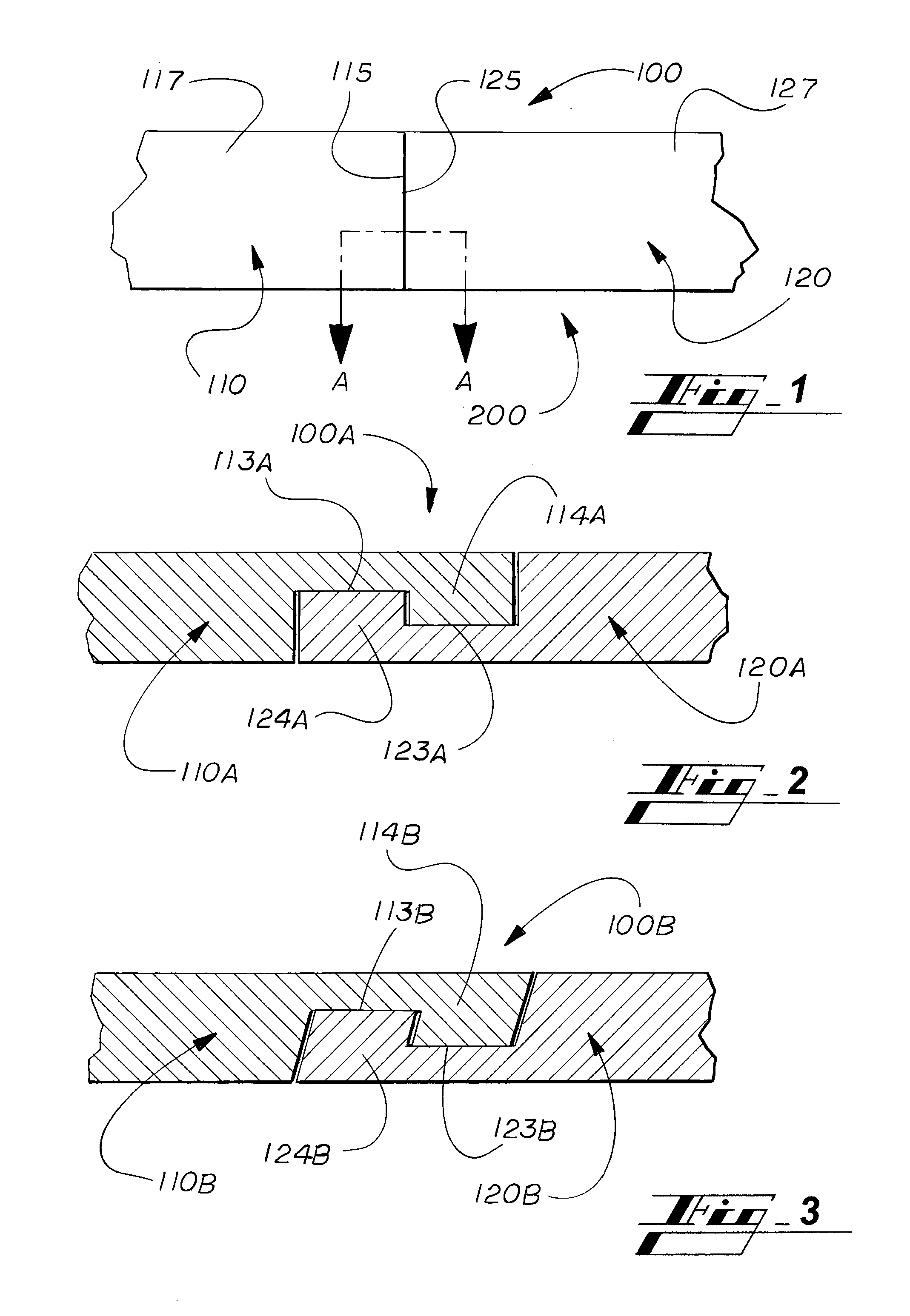
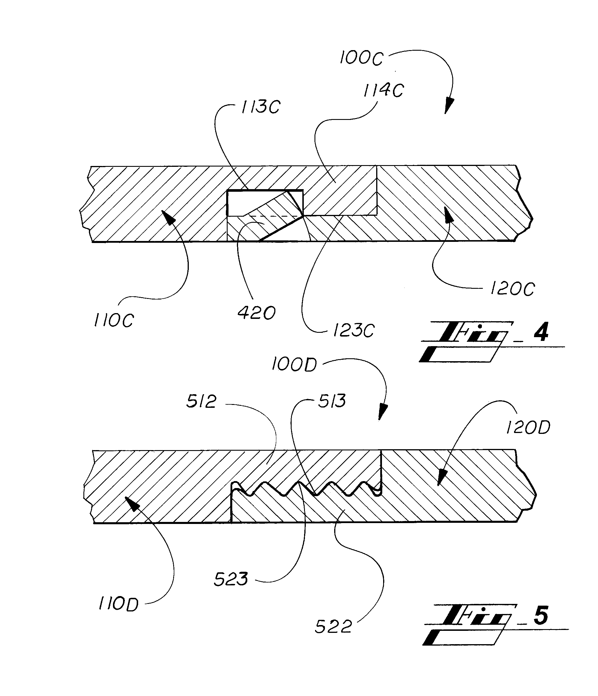
[0026]Generally speaking, as shown in FIG. 1, panel systems 100 of the present invention are generally flat sections used in building, construction and other applications, including in walls, siding, flooring, tiling, shelving, furniture and like. In one described but non-limiting embodiment, a panel system 100 of the invention includes siding panels 110 that have a plurality of horizontally adjacent siding panels 120 that are int...
PUM
Abstract
A panel system includes a pair of panels coupled together at corresponding vertical ends by a mechanical fastener accessory including first and second protrusions respectively piercing each panel to provide a composite panel with a substantially planar surface.
Description
CROSS REFERENCE TO RELATED APPLICATIONS[0001]The present application is a Division of U.S. patent application Ser. No. 13 / 898,539 filed on May 21, 2013, which is a Continuation-in-part of U.S. patent application Ser. No. 13 / 847,087 filed on Mar. 19, 2013, now U.S. Pat. No. 8,596,000, which is a Continuation of U.S. patent application Ser. No. 12 / 750,065 filed on Mar. 30, 2010, now U.S. Pat. No. 8,402,707, which claims the benefit of U.S. Provisional Application No. 61 / 299,383 filed on Jan. 29, 2010; and U.S. patent application Ser. No. 13 / 898,539 also claims the benefit of priority of U.S. Provisional Application No. 61 / 650,102 filed on May 22, 2012, all of which are incorporated herein by reference.BACKGROUND OF THE INVENTION[0002]1. Field of the Invention[0003]The present invention relates to panel systems, such as generally flat sections used in building, construction and other applications, including in walls, siding, flooring, tiling, shelving, furniture and like. In non-limiti...
Claims
Application Information
Patent Timeline
Application Date:The date an application was filed.
Publication Date:The date a patent or application was officially published.
First Publication Date:The earliest publication date of a patent with the same application number.
Issue Date:Publication date of the patent grant document.
PCT Entry Date:The Entry date of PCT National Phase.
Estimated Expiry Date:The statutory expiry date of a patent right according to the Patent Law, and it is the longest term of protection that the patent right can achieve without the termination of the patent right due to other reasons(Term extension factor has been taken into account ).
Invalid Date:Actual expiry date is based on effective date or publication date of legal transaction data of invalid patent.
Patent Type & AuthorityApplications(United States)

