Image shake correction device, control method thereof, and image pickup apparatus

Active Publication Date: 2016-01-21
CANON KK
View PDF3 Cites 2 Cited by
  • Summary
  • Abstract
  • Description
  • Claims
  • Application Information

AI Technical Summary

Benefits of technology

The image shake correction device can make multiple corrections simultaneously, by synchronizing the actions of multiple correction units. Its technical effects include improved image quality and smoother video footage.

Problems solved by technology

There are cases in which a subject image is shaken (image shake) due to the shaking of user's hand holding a camera body (causes hand shake) while capturing an image by an image pickup apparatus, such as a digital camera.
However, when the lens groups are integrally driven by using the same drive mechanisms as in the case of this image shooting lens, the arrangements of the lens, the arrangements of the drive mechanism, and like are restricted, and thus, the flexibility of design work may be lost.
However, when the drive phases of the lenses are not coincident, the deterioration of the optical performance occurs.
Accordingly, when the deterioration of the optical performance sometimes occurs, in particular during shooting a moving image and the like, the quality of the shot moving image is low.

Method used


Image

  • Image shake correction device, control method thereof, and image pickup apparatus
  • Image shake correction device, control method thereof, and image pickup apparatus
  • Image shake correction device, control method thereof, and image pickup apparatus

Examples


first embodiment

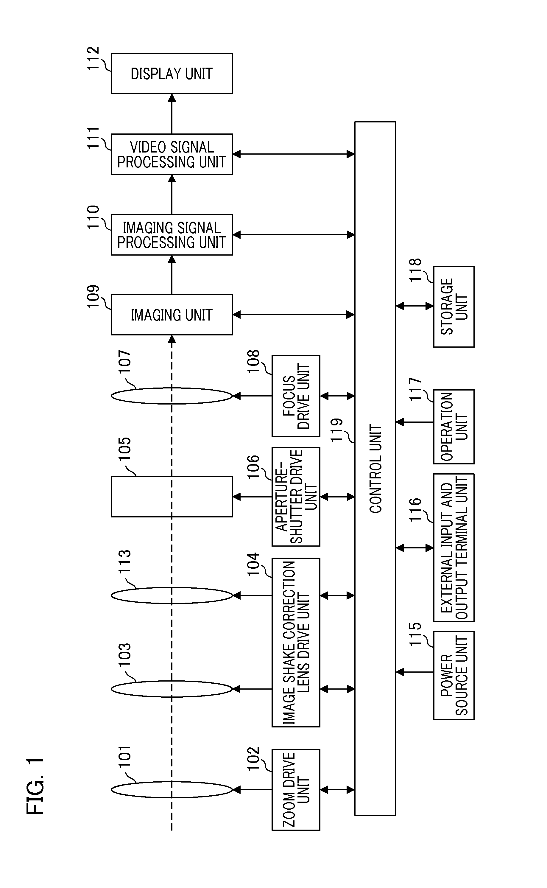
[0022]FIG. 1 is a diagram illustrating a configuration example of an image pickup apparatus of the present embodiment. The image pickup apparatus shown in FIG. 1 is a digital still camera. Note that the image pickup apparatus of the present embodiment may have a moving image shooting function.

[0023]The image pickup apparatus shown in FIG. 1 comprising a zoom unit 101, a zoom drive unit 102, a first image shake correction lens 103, an image shake correction lens drive unit 104, an aperture / shutter unit 105, an aperture / shutter drive unit 106, a focus lens 107, a focus drive unit 108, an imaging unit 109, an imaging signal processing unit 110, a video signal processing unit 111, a display unit 112, a second image shake correction lens 113, a power source unit 115, an external input and output terminal unit 116, an operation unit 117, a storage unit 118, and a control unit 119. The zoom unit 101 is a part of a variable magnification image shooting lens that configures an imaging optica...

second embodiment

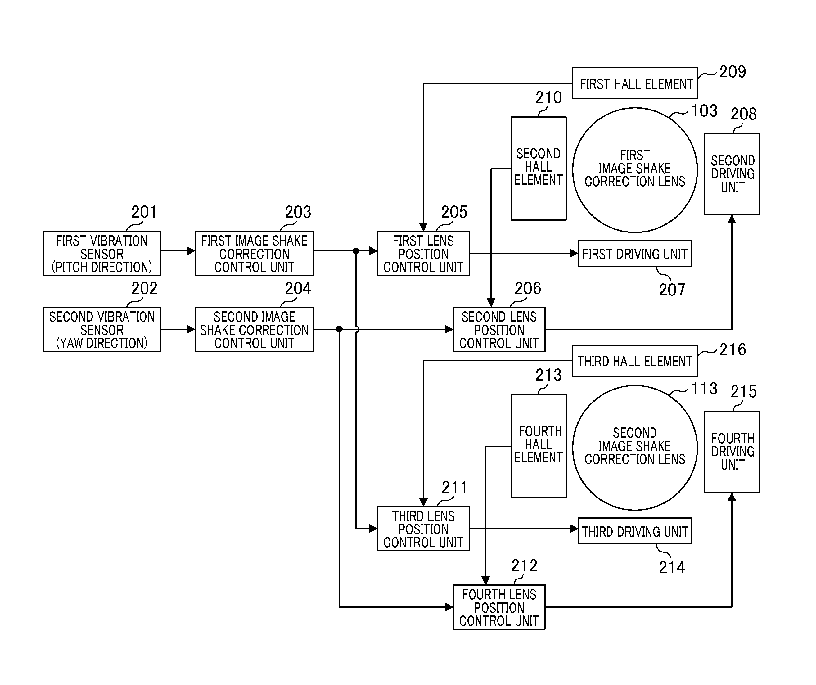
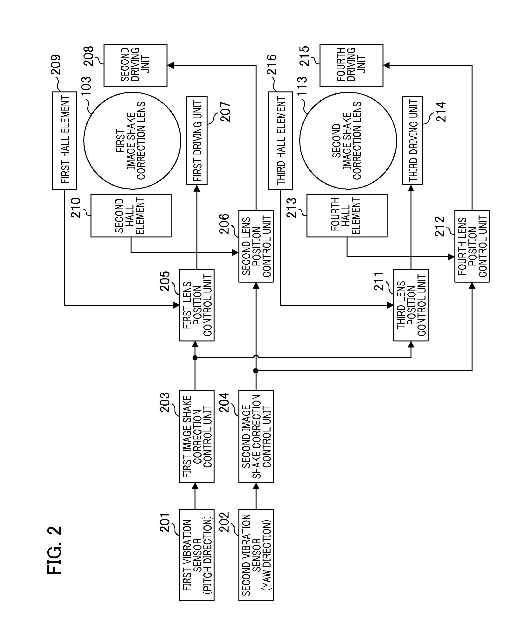
[0064]FIG. 8 is a diagram illustrating an internal configuration of the image shake correction device of the second embodiment. The configuration of the image shake correction device of the second embodiment, except for the image shake correction control unit 203, is similar to the first embodiment, and thus, the explanation thereof will be omitted. The second image shake correction control unit 204, the second lens position control unit 206, and the fourth lens position control unit 212 have similar configurations as the configurations shown in FIG. 8, and thus, the explanation thereof will be omitted.

[0065]As shown in FIG. 8A, the image shake signal detected by the first vibration sensor 201 is integrated by the LPF 501, and converted into the angle information (image shake angle signal) by using the angular velocity information. The image shake angle signal is input to the first lens position control unit 205 serving as the target position of the first image shake correction lens...


PUM


Abstract

An image shake correction device comprising a first image shake correction lens and a second image shake correction lens for correcting an image shake of a subject image caused by shaking is provided. The image shake correction device executes correcting the image shake caused by the drive of the first image shake correction lens and the second image shake correction lens after correcting a drive deviation between the first image shake correction lens and the second image shake correction lens.

Description

BACKGROUND OF THE INVENTION[0001]1. Field of the Invention[0002]The present invention relates to an image shake correction device, a control method thereof, and an image pickup apparatus.[0003]2. Description of the Related Art[0004]There are cases in which a subject image is shaken (image shake) due to the shaking of user's hand holding a camera body (causes hand shake) while capturing an image by an image pickup apparatus, such as a digital camera. There has been proposed an image pickup apparatus comprising an image shake correction unit that corrects this image shake.[0005]Optical image shake correction processing and electronic image shake correction processing have conventionally been used as correction processing by the image shake correction unit. The optical image shake correction processing detects a vibration applied to the camera body by using, for example, an angular velocity sensor, and moves an image shake correction lens, which is provided inside an imaging optical sy...

Claims


Application Information

Patent Timeline
IPC IPC(8): G02B27/64H04N5/232
CPCH04N5/23287G02B27/646H04N23/6812H04N23/687
Inventor TAKEUCHI, KENJI
Owner CANON KK
Why Eureka
Try Eureka