Card holding member and card connector

a holding member and card technology, applied in the direction of coupling device connection, coupling/disengagement parts, instruments, etc., can solve the problems of relative large amount of force to be exerted, difficult to insert the card tray b>961, and difficult to eject the card tray b>961

Active Publication Date: 2016-02-04
MOLEX INC
View PDF5 Cites 25 Cited by
  • Summary
  • Abstract
  • Description
  • Claims
  • Application Information

AI Technical Summary

Benefits of technology

[0011]It is an object of the present disclosure to provide a card holding member and a card connector able to reliably hold the card holding member in the card connector and readily eject the card holding member so that an auxiliary member activated by the ejection mechanism disengages a lock portion when the ejection operation is performed to eject the card holding member from the card connector.
[0021]In the present disclosure, a card connector can reliably hold a card holding member in the card connector and readily eject the card holding member so that an auxiliary member activated by the ejection mechanism disengages a lock portion when the ejection operation is performed to eject the card holding member from the card connector.

Problems solved by technology

Therefore, a relatively large amount of force has to be exerted to slide the push rod using a small auxiliary member, and this makes it difficult to eject the card tray 961.
However, when the user manually pushes in the front surface of the flange portion 963, which is larger than the auxiliary member, it is difficult to insert the card tray 961 even when a fairly large amount of force is exerted.

Method used


Image

  • Card holding member and card connector
  • Card holding member and card connector
  • Card holding member and card connector

Examples


second embodiment

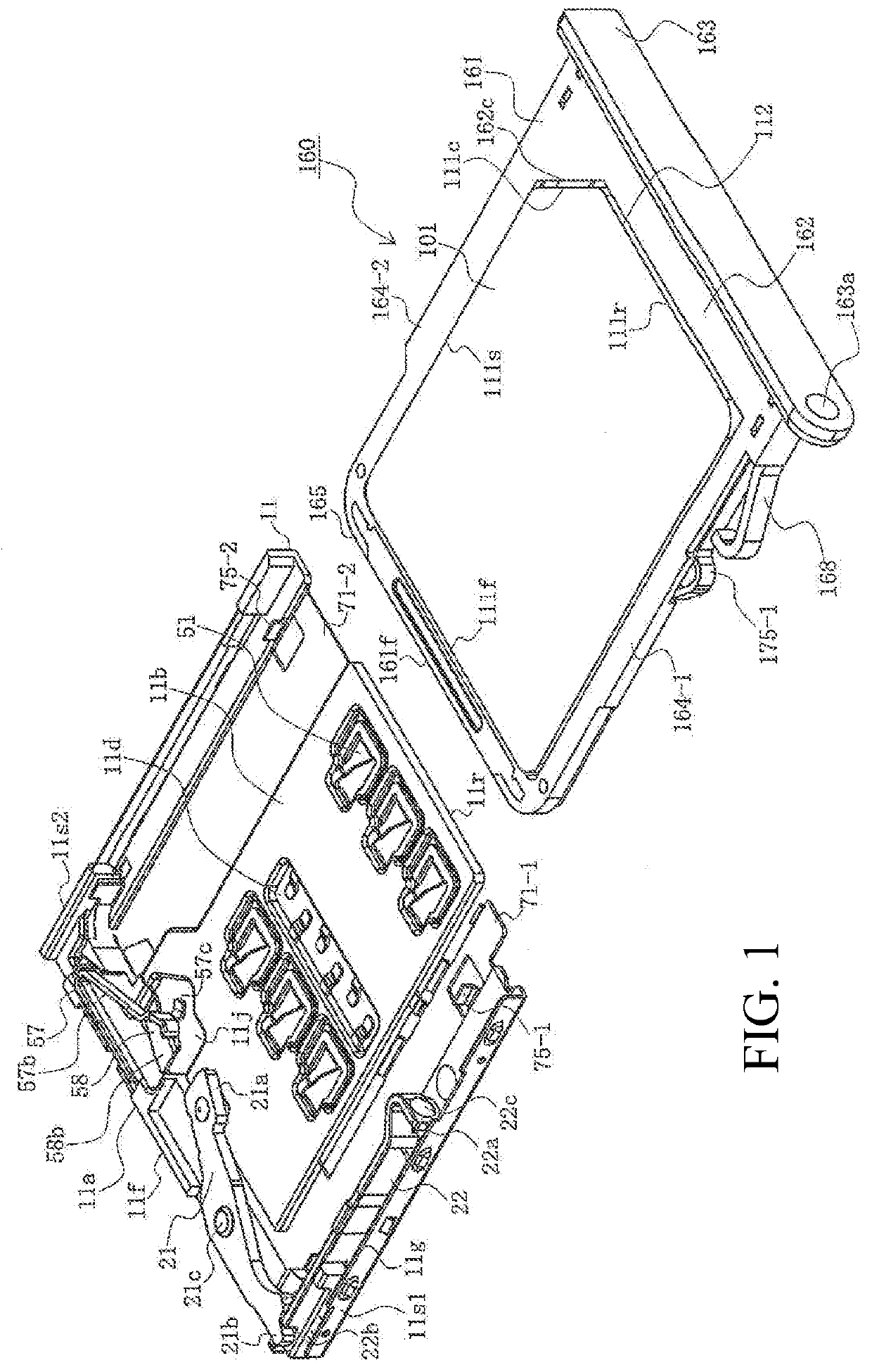
[0110]FIG. 8 is a perspective view of the card connector in the present disclosure showing the situation immediately before the card tray is inserted.

first embodiment

[0111]Because the card 101 in the present embodiment is identical to the card 101 in the first embodiment, further explanation has been omitted.

[0112]The card connector 1 of the present embodiment does not have a first holding engaging piece 75-1 and a second holding engaging piece 75-2 formed in a first flange portion 71-1 and a second flange portion 71-2. Instead, a holding engaging opening 65 is formed as a fixed lock portion in the ceiling panel portion 62 of the shell 61. The holding engaging opening 65 is positioned above the holding member 176 in the card tray 160 inserted into the card connector 1 as a movable lock portion. The edge of the holding engaging opening 65 near the rear end portion 61r functions as an engaging edge portion 65a. Because the rest of the configuration of the card connector 1 in the present embodiment is identical to that of the first embodiment, further explanation has been omitted.

[0113]As in the case of the card tray 160 in the present embodiment, ...

third embodiment

[0136]FIG. 10 is a perspective view of the card connector in the present disclosure showing the situation immediately before the card tray is inserted.

[0137]Because the card 101 in the present embodiment is identical to the card 101 in the first embodiment, further explanation has been omitted.

[0138]The card connector 1 of the present embodiment does not have a first holding engaging piece 75-1 and a second holding engaging piece 75-2 formed in a first flange portion 71-1 and a second flange portion 71-2. Instead, a holding engaging opening 65 is formed as a fixed lock portion in the ceiling panel portion 62 of the shell 61. The holding engaging opening 65 is positioned above the holding member 177 in the card tray 160 inserted into the card connector 1 as a movable lock portion. The opening is substantially rectangular and passes through the ceiling panel portion 62 in the thickness direction. The edge of the holding engaging opening 65 near the rear end portion 61r functions as an...


PUM


Abstract

A card holding member is able to hold a card 101 with terminal members and able to be inserted into a card connector. Here, the card holding member includes a frame portion 161 facing a side surface 112 of the card 101, and a movable lock portion provided on the frame portion 161 which is able to engage and disengage a lock portion of the card connector. The movable lock portion is disengaged from the lock portion by an auxiliary portion which activates the ejection mechanism for ejecting the card holding member from the card connector.

Description

RELATED APPLICATIONS[0001]This application claims priority to Japanese Patent Application No. 2014-157351, filed Aug. 1, 2014, which is incorporated herein by reference in its entirety.FIELD OF THE INVENTION[0002]The present disclosure relates to a card holding member and a card connector.DESCRIPTION OF RELATED ART[0003]Electronic devices such as personal computers, cell phones, personal digital assistants (PDAs), digital cameras, video cameras, music players, gaming devices and car navigation systems include connectors that allow various types of devices to be used. These include Subscriber Identity Module (SIM) cards, Multi-media Cards® (MMC), Secure Digital® (SD) cards, miniSD® cards, xD-Picture® cards, Memory Sticks®, Memory Stick Duo®, Smart Media®, Trans-Flash® memory cards, and MicroSD® cards.[0004]Electronic devices have become significantly smaller in recent years, and so have cards and card connectors. As a result, it can be difficult for users to grasp a card with the fin...

Claims


Application Information

Patent Timeline
Patent Type & Authority Applications(United States)
IPC IPC(8): H01R12/70H01R13/633
CPCH01R13/6335H01R12/7076H01R13/635G06K13/08
Inventor MOTOHASHI, NOBUMASASHIMOTSU, AKIHIROUKITA, NOBUKI
Owner MOLEX INC
Why Eureka
Try Eureka