Blast Control Blanket

a technology of blast control and blanket, which is applied in the direction of blasting, protective equipment, weapons, etc., to achieve the effect of maximum protection and easy modification

Inactive Publication Date: 2016-02-11
BLAST CONTROL SYST L L C
View PDF2 Cites 38 Cited by
  • Summary
  • Abstract
  • Description
  • Claims
  • Application Information

AI Technical Summary

Benefits of technology

[0016]The present invention addresses these problems by providing a relatively lightweight, modular, blast control system which utilizes a plurality of fabric panels that may be joined to form a matrix or blanket to protect or control the blast. The use of fabric panels enables the size of the blast control system to be variable and easily modified depending on specific requirements; the size may be adjusted to become larger or smaller depending on the unique blast control scenario encountered. Each panel may be manufactured from different types of high-strength, cut-resistant fabric that is designed to stretch and absorb a large amount of energy during a blast or other event, and still provide maximum protection as the fabric stretches, particularly at the point where projectiles may impact the fabric from the blast or event. The panels may be connected together via a locking mechanism or assembly comprising a cable and pin assembly in order to form the fully assembled blast control blanket.

Problems solved by technology

Further, due to the auxetic structure of the fabric and negative Poisson's ratio exhibited, the fabric tends to form a cup for catching and containing both the shockwave of an explosion as well as shrapnel and projectiles.

Method used


Image

  • Blast Control Blanket
  • Blast Control Blanket
  • Blast Control Blanket

Examples


Embodiment Construction

[0044]The following description is presented to enable any person skilled in the art to make and use the invention, and is provided in the context of a particular application and its requirements. Various modifications to the disclosed embodiments will be readily apparent to those skilled in the art, and the general principles defined herein may be applied to other embodiments and applications without departing from the spirit and scope of the present invention. Thus, the present invention is not intended to be limited to the embodiments shown, but is to be accorded the widest scope consistent with the principles and features disclosed herein. Additionally, as used herein, the term “substantially” is to be construed as a term of approximation.

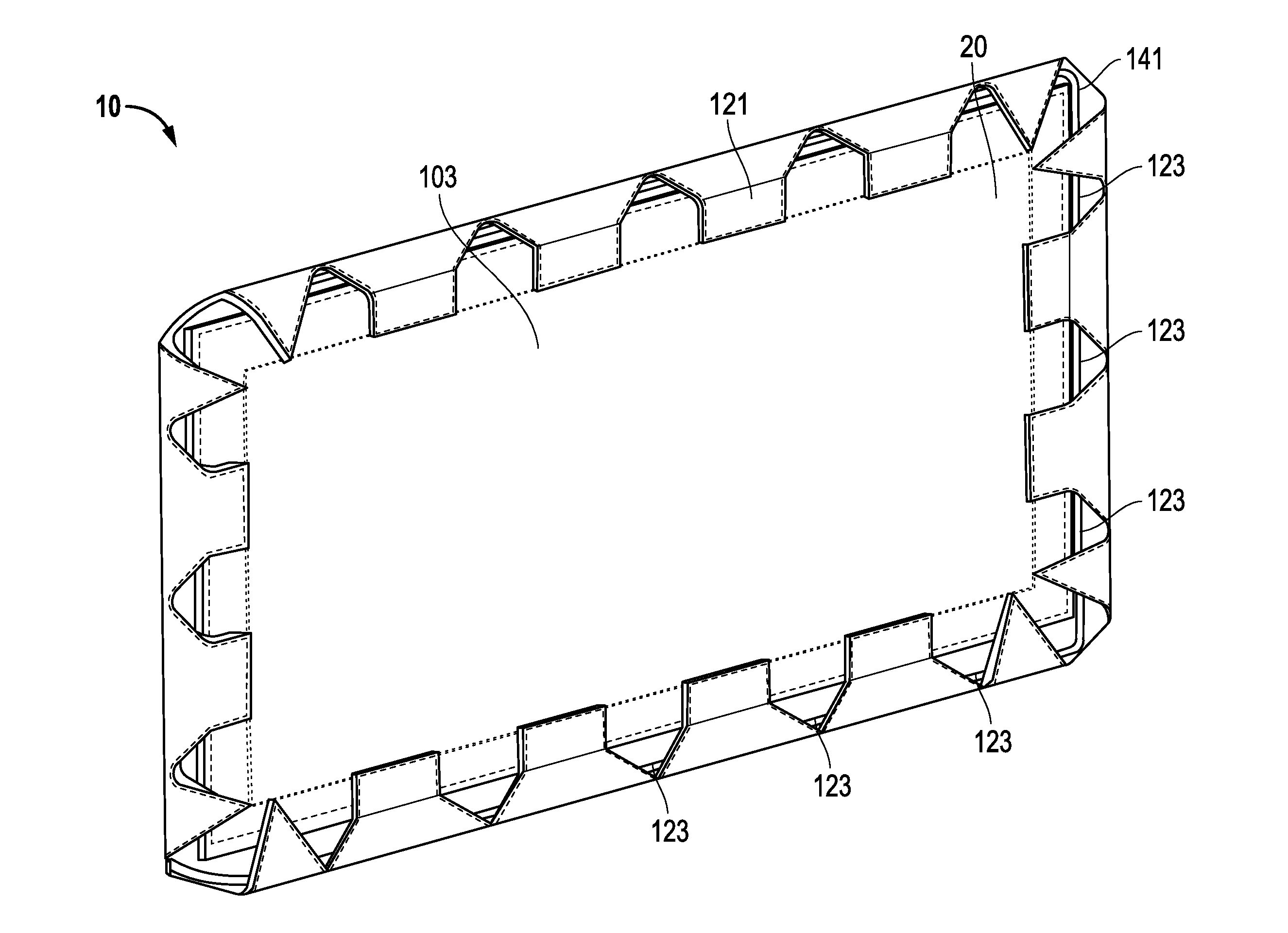
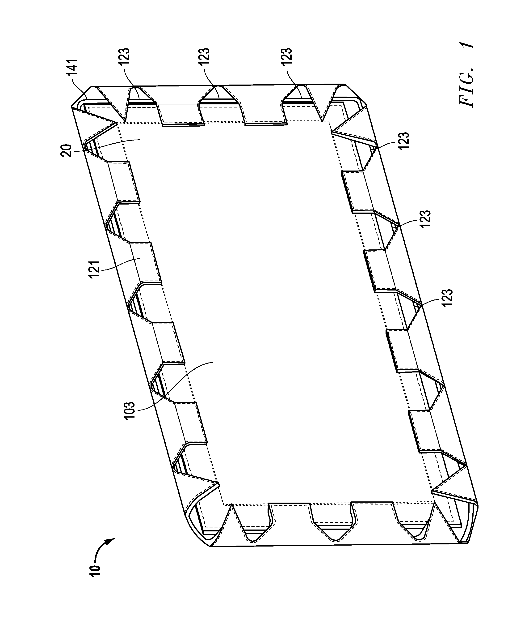
[0045]Referring to FIG. 1, there is shown a perspective view of an assembled fabric panel 10 of the present invention. The fabric panel 10 may be comprised of at least two or more layers of a blast resistant fabric. The two or more layers of a ...


PUM

PropertyMeasurementUnit
velocitiesaaaaaaaaaa
widthaaaaaaaaaa
angleaaaaaaaaaa

Abstract

A blast control blanket is provided. The blanket has a first tubular fabric layer and a second tubular fabric layer. Each tubular fabric layer has a circumferential weave direction. The tubular fabric layers are oriented so that their weave directions are orthogonal. The tubular fabric layers are preferably an auxetic woven fabric. Optionally, smaller fabric sections may be seamed together to form each tubular fabric layer. The tubular fabric layers are stitched together so as to form a perimeter channel. A wire cable is disposed in the perimeter channel and may be used to secure multiple blankets together or secure the blanket to another structure. Optionally, an outer cover may be provided, preferably of ballistic nylon.

Description

CROSS-REFERENCE TO RELATED APPLICATION[0001]This application claims the benefit of U.S. Provisional Application No. 62 / 044,072, filed Aug. 29, 2014, and is also a continuation-in-part of U.S. application Ser. No. 14 / 072,549, filed on Nov. 5, 2013, which is a divisional application of U.S. application Ser. No. 13 / 549,121, filed Jul. 13, 2012; each of which are hereby incorporated by reference in their entirety.TECHNICAL FIELD OF INVENTION[0002]The invention relates generally to a system and method for a blast control blanket for controlling an explosive blast.BACKGROUND OF THE INVENTION[0003]In industries where explosive or pressure testing may be necessary, it is common to build blast mitigation and protection systems around equipment to be pressure tested. In addition, there may be circumstances where equipment may be overspeed tested which may result in situations where flying objects of small to significant size and velocities up to 1000 feet per second are produced, thus also ne...

Claims


Application Information

Patent Timeline
Patent Type & Authority Applications(United States)
IPC IPC(8): F41H5/04B32B5/06
CPCF41H5/0442B32B5/06F41H5/0478F41H5/0485F42D5/05
Inventor ROSSOW, RICHARDBALLEW, CHERIVERMA, VIKAS
Owner BLAST CONTROL SYST L L C
Why Eureka
Try Eureka