
Ankle brace

a technology for ankle bones and braces, applied in non-surgical orthopedic devices, medical science, footwear, etc., can solve the problems of pressure, rubbing and irritation of protruding ankle bones, and the inability to separate the circular hinge devi

Active Publication Date: 2016-02-18
NAYFA TERRY M
View PDF5 Cites 5 Cited by
  • Summary
  • Abstract
  • Description
  • Claims
  • Application Information

AI Technical Summary

Benefits of technology

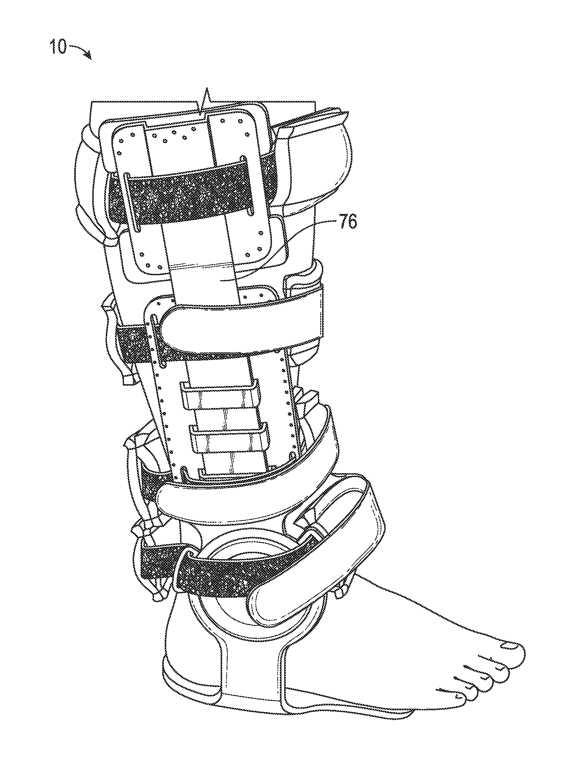
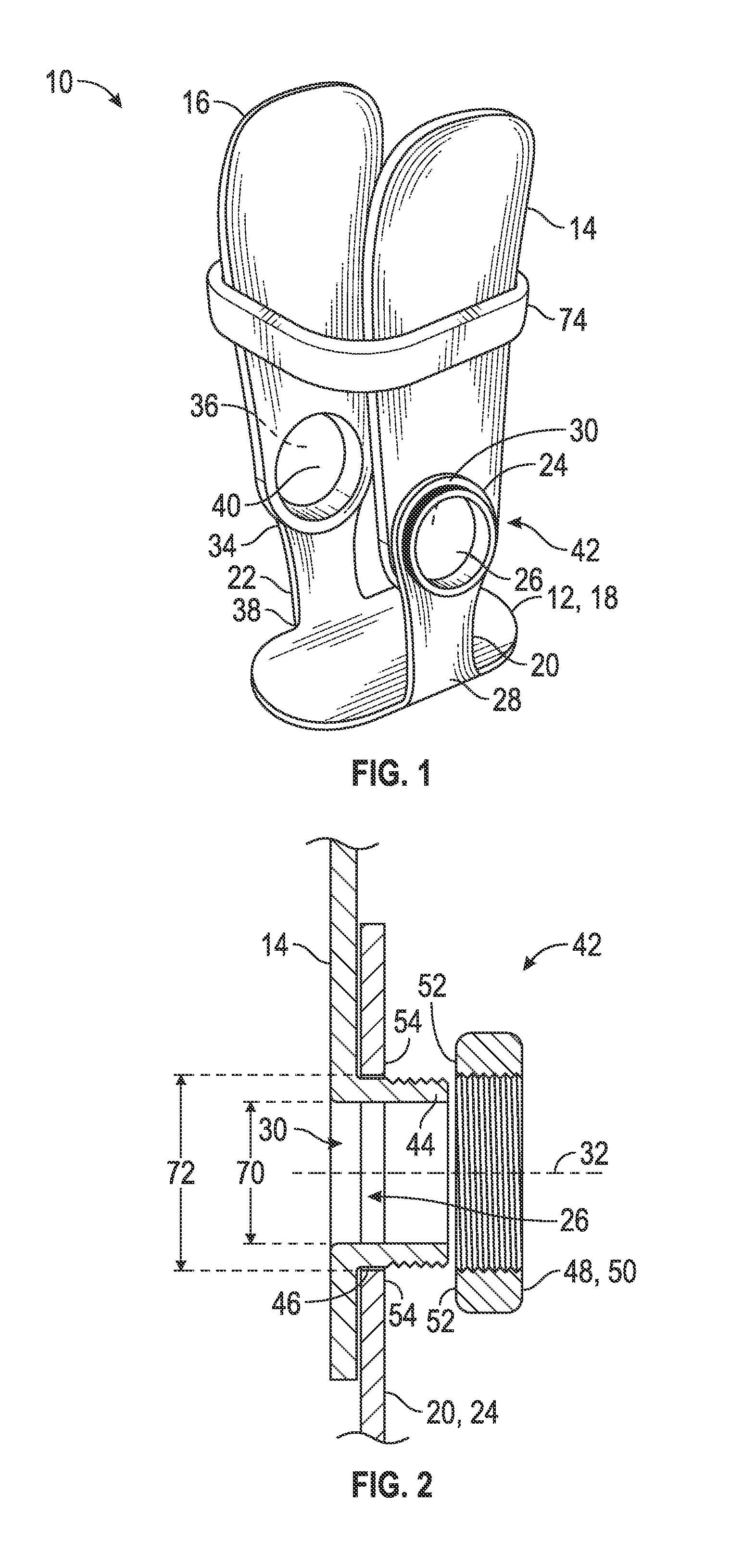
This patent is about an ankle brace that has a stirrup and two pivot legs. The stirrup has a flat bottom and two upright legs with circular openings at the top and bottom. The pivot legs are connected to the upright legs and can rotate around their own axes. This design allows the brace to fit snugly around an ankle bone and provide support. Additional support can be provided by attaching leg extensions to the pivot legs. This ankle brace is designed to help protect ankle bones from injury.

Problems solved by technology

Unfortunately, location of a hinge or rivet adjacent the ankle bone can cause pressure, rubbing and irritation of the protruding ankle bones.
Unfortunately, this circular hinge device is not separable.
However, prior art ankle braces having detachable hinges are bulky and require the detachable hinge surface to rotate about the ankle bone when worn, causing irritation as described above.

Method used


Image

  • Ankle brace
  • Ankle brace
  • Ankle brace

Examples


Embodiment Construction

[0028]Before explaining at least one embodiment of the inventive concepts disclosed herein in detail, it is to be understood that the inventive concepts are not limited in their application to the details of construction, experiments, exemplary data, and / or the arrangement of the components set forth in the following description, or illustrated in the drawings. The presently disclosed and claimed inventive concepts are capable of other embodiments or of being practiced or carried out in various ways. Also, it is to be understood that the phraseology and terminology employed herein is for purpose of description only and should not be regarded as limiting in any way.

[0029]In the following detailed description of embodiments of the inventive concepts, numerous specific details are set forth in order to provide a more thorough understanding of the inventive concepts. However, it will be apparent to one of ordinary skill in the art that the inventive concepts within the disclosure may be...


PUM


Abstract

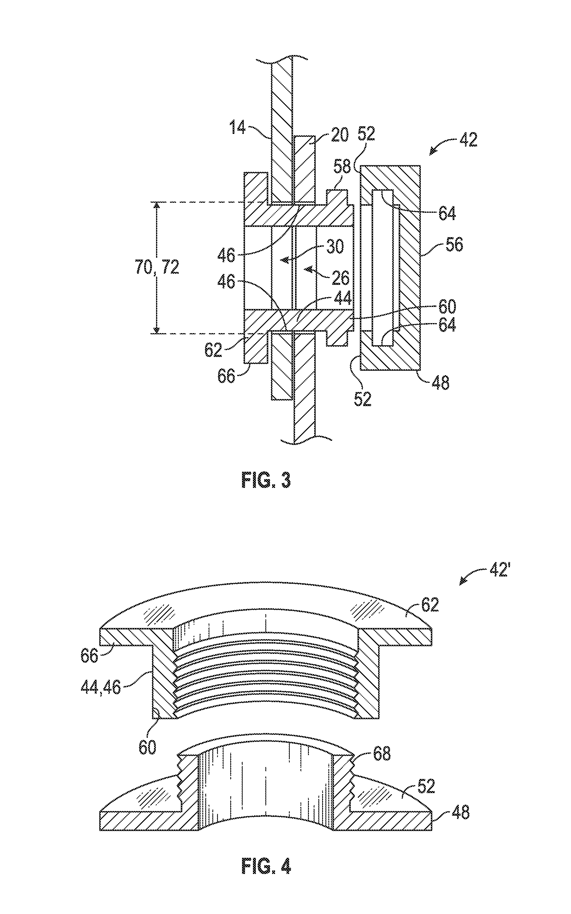
An ankle brace has a stirrup with a flat bottom portion and a first and second upright leg. Each of the first and second upright legs has an upper end and a lower end, the upper end having a circular opening therethrough and the lower end attached to the flat bottom portion. First and second pivot legs, each having a circular opening therethrough, are removeably and rotatably connected to the first and second upright legs respectively. First and second leg extensions are removeably connected to the first and second pivot legs, respectively. When connected, the circular openings in the pivot legs overlap the respective circular openings in the upright legs, and each pivot leg is rotatable about an axis through and perpendicular to the pivot leg circular opening. The circular openings in the first and second upright legs are positioned and sufficiently large to allow at least a portion of the malleolus bone of an ankle to protrude therethrough.

Description

CROSS-REFERENCE TO RELATED APPLICATIONS / INCORPORATION BY REFERENCE STATEMENT[0001]This application is a continuation-in-part of U.S. Ser. No. 13 / 674,212 filed Nov. 12, 2012, and also claims priority to U.S. provisional application Ser. No. 62 / 069,621 filed Oct. 28, 2014, the contents each of which are hereby incorporated in their entirety.BACKGROUND OF THE INVENTIVE CONCEPTS[0002]1. Field of the Inventive Concepts[0003]The inventive concepts disclosed and claimed herein relate generally to orthopedic devices, and more particularly, but not by way of limitation, to an ankle brace.[0004]2. Brief Description of Related Art[0005]Ankle injuries are among the most common injuries in sports. When an ankle is injured, the traditional methods for promoting healing include application of pressure to the area to reduce swelling and to prevent movement of the ankle. The current trend in medicine now is to promote exercise as soon as possible after an ankle injury. It is therefore desirable to p...

Claims


Application Information

Patent Timeline
Patent Type & Authority Applications(United States)
IPC IPC(8): A61F5/01
CPCA61F5/0127A61F5/0195A61F2005/0165A61F2005/0158A61F2005/0137A61F5/0102A43B7/20
Inventor NAYFA, TERRY, M.
Owner NAYFA TERRY M
Learn More