Spring-force clamping element with pivoting lever

a technology of pivoting lever and clamping element, which is applied in the direction of coupling contact member, securing/insulating coupling connection, electrical equipment, etc. it can solve the problems of uneven actuation force on the spring, large installation depth, and spring flexing toward the outer edge, so as to facilitate the removal of electrical conductors, reduce the force required for actuating the clamping limb, and reduce the effect of installation heigh

Active Publication Date: 2016-02-18
WEIDMULLER INTERFACE GMBH & CO KG
View PDF8 Cites 12 Cited by
  • Summary
  • Abstract
  • Description
  • Claims
  • Application Information

AI Technical Summary

Benefits of technology

[0017]In one particularly preferred embodiment, the lateral operating projection is disposed between the release lever ends, and preferably adjacent the mounting end. As a result, an open end of the clamping limb is freely movable when the clamping point is opened, thereby making it easy to remove the electrical conductor.
[0018]The pivoting lever is preferably mounted on the axial limb so as to be rotatable about the pivot axis. An actuating surface is also preferably provided on the actuating leg. In this way, the mechanical advantage is proved that lever travel is relatively long and the force required for actuating the clamping limb is relatively minimal It is preferable that the actuating surface be designed for actuation with or without the use of an actuating tool.
[0019]The spring clamping

Problems solved by technology

However, the extension of the spring arm of the Chiang patent requires a comparatively wide spring and, therefore, a large installation depth.
And with the application of force on th

Method used


Image

  • Spring-force clamping element with pivoting lever
  • Spring-force clamping element with pivoting lever
  • Spring-force clamping element with pivoting lever

Examples


Embodiment Construction

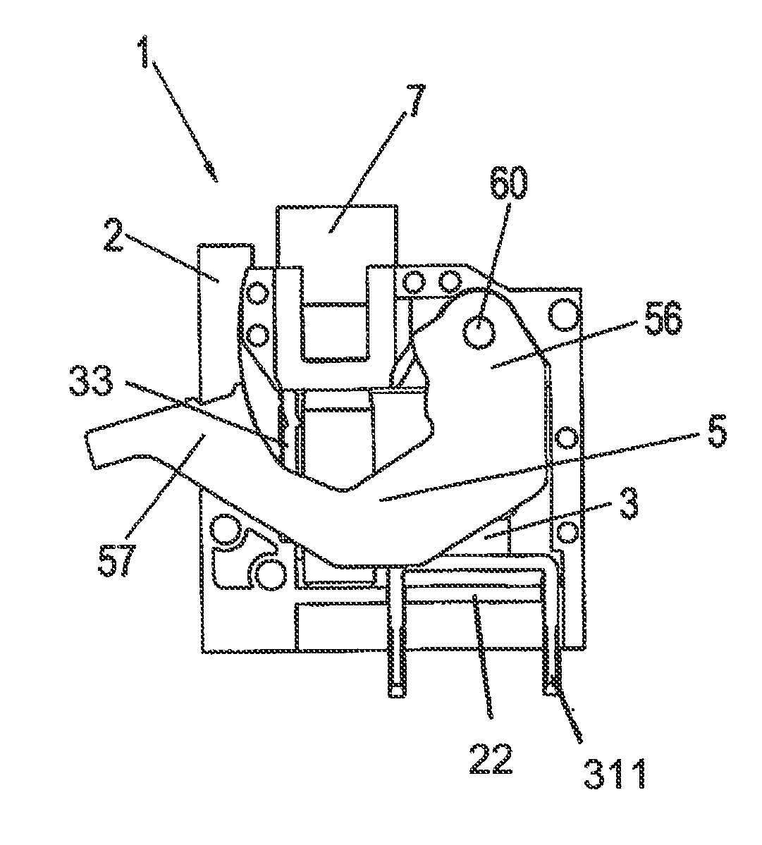
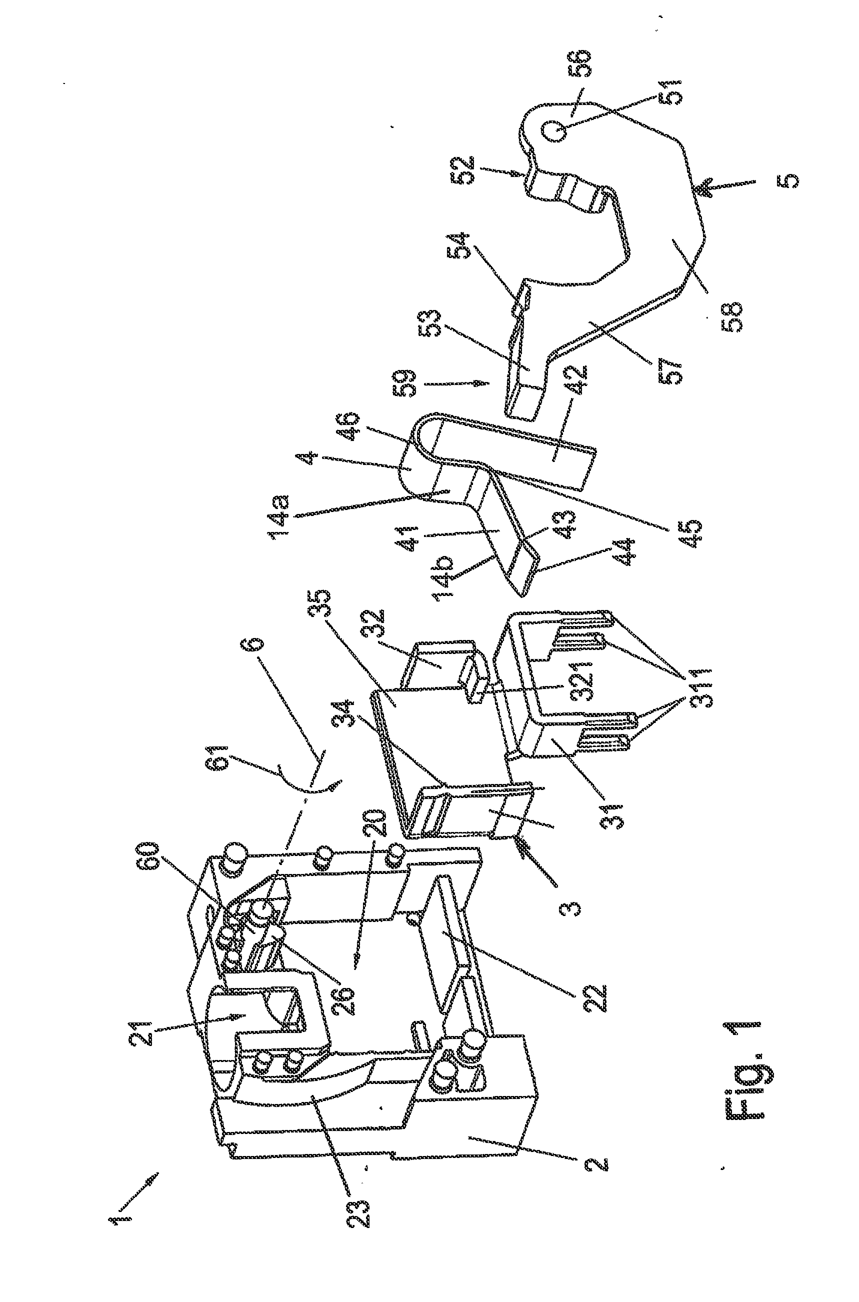
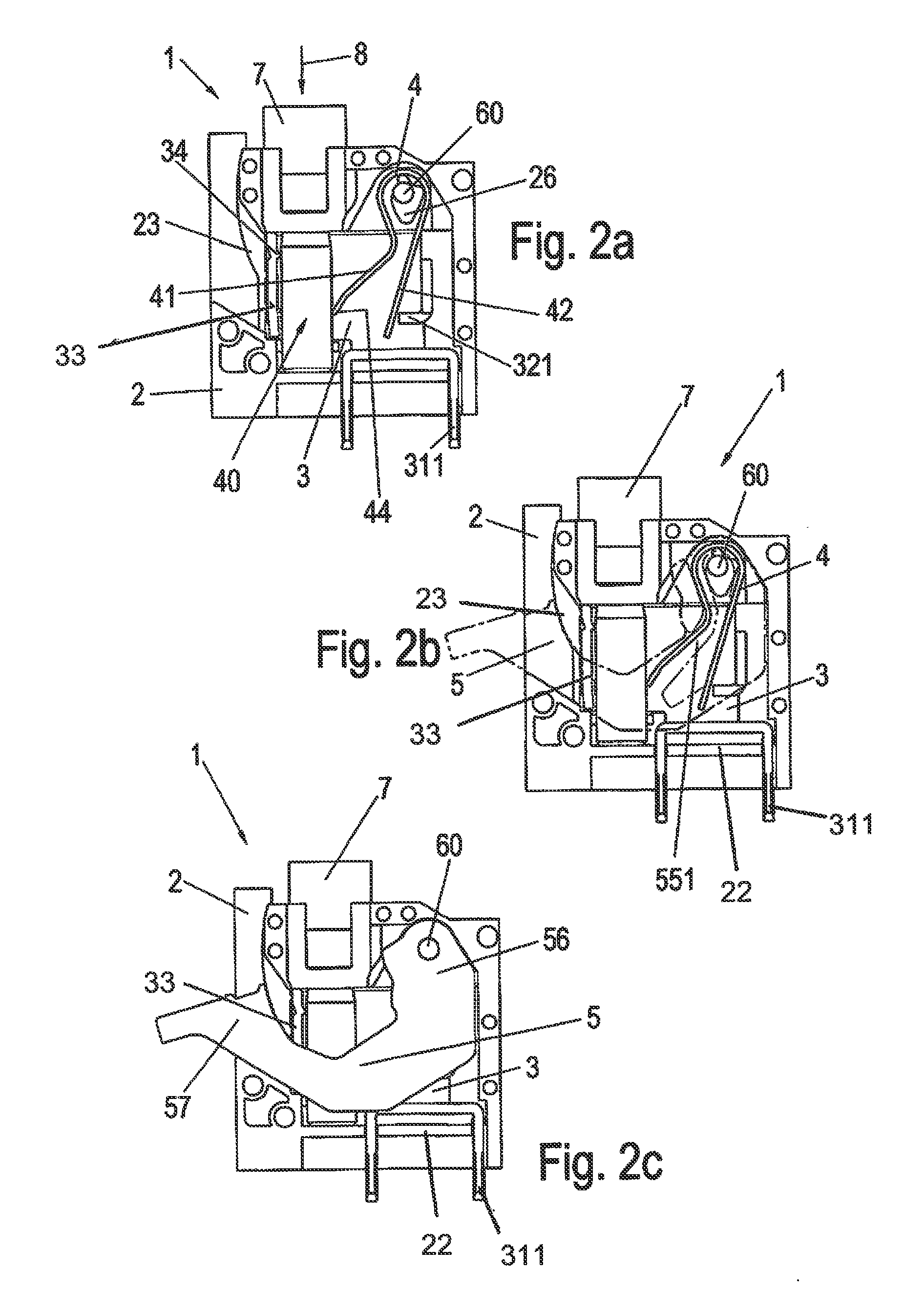
[0026]Referring first more particularly to FIG. 1 as an overview, the connector arrangement 1 of the present invention includes a housing 2 formed of a non-conductive synthetic plastic material, and includes a vertical bottom wall and side walls cooperating to define a chamber 20 in which are mounted a conductive cage member 3 and a clamping spring 4. As shown in FIGS. 2c and 2f, the front of the chamber is partially closed by a release lever 5 that is pivotally connected with the housing by a pivot shaft 60. An access opening 21 is provided in the side walls of the housing to permit the bare end of an insulated conductor 8 to be inserted into and removed from the housing chamber 21. The conductor 8 can be a single-wire conductor, or a braided wire conductor. In the case of a braided wire conductor, a protective funnel-shaped conductive support sleeve 7 is provided for introducing the bare conductor end into the housing chamber 20.

[0027]The conductive cage member 3, has a generally ...


PUM


Abstract

A compact spring-biased connector includes a housing having a chamber containing a conductive bus bar, a clamping spring normally having an expanded clamping condition for biasing a conductor bare end toward electrical engagement with the bus bar, and a release lever pivotally connected with the housing for displacement from a normally closed clamping position toward an open position, such that a lateral projection on the clamping lever operates the clamping spring toward a compressed open condition, thereby permitting removal of the conductor bare end from the housing chamber. The clamping spring is a compression V-shaped leaf spring having a stationary support leg and a movable clamping leg, with the lateral operating projection extending within the chamber to engage the spring clamping leg adjacent its juncture with the support leg.

Description

REFERENCE TO RELATED APPLICATIONS[0001]This application is a national stage application under 35 C.F.R. §371 of the PCT International Application No. PCT / EP2014 / 057531 filed Apr. 14, 2014, which claims priority of the German application No. DE 20 2013 101 582.2 filed Apr. 15, 2013.BACKGROUND OF THE INVENTION[0002]1. Field of the Invention[0003]The present invention relates to a spring-biased connector including a housing having a chamber containing a conductive bus bar, and a clamping spring normally having an expanded clamping condition for biasing a conductor bare end toward electrical engagement with the bus bar. A release lever is pivotally connected with the housing for displacement from a normal closed clamping position toward an open position, whereby a lateral projection on the clamping lever operates the clamping spring from the expanded clamping condition toward a compressed open condition, thereby to permit removal of the conductor bare end from the housing chamber.[0004...

Claims


Application Information

Patent Timeline
IPC IPC(8): H01R4/48H01R13/633
CPCH01R13/633H01R4/4809H01R4/48365
Inventor APORIUS, STEFANCLASSEN, CONTANTINHANKE, DIRKNOLTE, SASCHA
Owner WEIDMULLER INTERFACE GMBH & CO KG
Why Eureka
Try Eureka