Subcutaneous sensor inserter and method

a sensor and subcutaneous technology, applied in the field of glucose monitoring sensors, can solve the problems of slow adoption of glucose monitoring devices by many patients, cgm user forums comparing and critiquing current available devices for their pain of deployment, and likely to trigger a pain response, so as to minimize pain, minimize the peak force of insertion, and minimize the effect of pain

Active Publication Date: 2016-03-03
SANVITA MEDICAL CORPORATION
View PDF6 Cites 42 Cited by
  • Summary
  • Abstract
  • Description
  • Claims
  • Application Information

AI Technical Summary

Benefits of technology

[0020]Reducing or minimizing insertion pain is one criterion for patient acceptance of any continuous monitoring system. Other criteria include the convenience and ease-of-use of the inserter device. Therefore, a need exists for an inserter set and an inserter assembly that reduces or minimizes the patient's pain and inconvenience of inserting a continuous monitoring sensor. The present invention achieves these and other objectives by providing a continuous analyte monitoring inserter apparatus for subcutaneous placement of a sensor into a patient and a sharp / needle that minimizes insertion pain with a reduced cross-sectional area.
[0048]In another aspect of the present invention, a continuous analyte monitoring inserter apparatus for subcutaneous placement of a sensor into skin of a patient minimizes pain to a patient. In one embodiment, the apparatus has a single action inserter assembly having a housing body with a first body end and a second body end. A deployment button is partially disposed in and slidable within the housing body through the first body end, where the deployment button being movable between a first position and a second position. A sensor housing is partially disposed within and removably retained in the second body end. A needle is movably disposed within the single action inserter assembly. The needle has a cross-sectional shape that minimizes a peak force of insertion into the skin of the patient. An implantable sensor is partially disposed within the needle. The inserter assembly is adapted to substantially simultaneously implant the sensor subcutaneously into the patient, retract the needle, fix the sensor within the sensor housing and release the inserter assembly from the sensor housing with a single activation of the deployment button caused by moving the deployment button from the first position to the second position while minimizing pain to the patient.
[0052]In another aspect of the present invention is a method of minimizing pain when inserting an in-vivo analyte sensor subcutaneously for continuous analyte monitoring of a patient. In one embodiment, the method includes providing a single action inserter assembly having a needle with a cross-sectional shape that minimizes a peak force of insertion into the skin of the patient, an implantable sensor, a deployment button for implanting the implantable sensor using the needle and for retracting the needle, and a sensor housing for retaining the implanted sensor in an implanted orientation once deployed by the deployment button; and using a single action to activate the deployment button of the single action inserter assembly that causes the following actions to substantially simultaneously occur: (1) implanting the sensor subcutaneously into the patient, (2) fixedly seating the sensor within the sensor housing attached to the patient, (3) retracting the needle used to implant the sensor into the inserter assembly, and (4) releasing the inserter assembly from the sensor housing, wherein the needle and the single action minimizes pain when inserting the sensor subcutaneously.

Problems solved by technology

Continuous glucose monitoring (CGM) devices have been slow to be adopted by many patients due to the pain and long term discomfort of initial deployment and long term use (3 to 7 days).
Currently available devices are commonly compared and criticized on CGM user forums for their pain of deployment.
With nociceptors located throughout the thickness of the epidermis, a deeper incision is more likely to trigger a pain response due to the increased likelihood of trauma to more nociceptors.

Method used


Image

  • Subcutaneous sensor inserter and method
  • Subcutaneous sensor inserter and method
  • Subcutaneous sensor inserter and method

Examples


Embodiment Construction

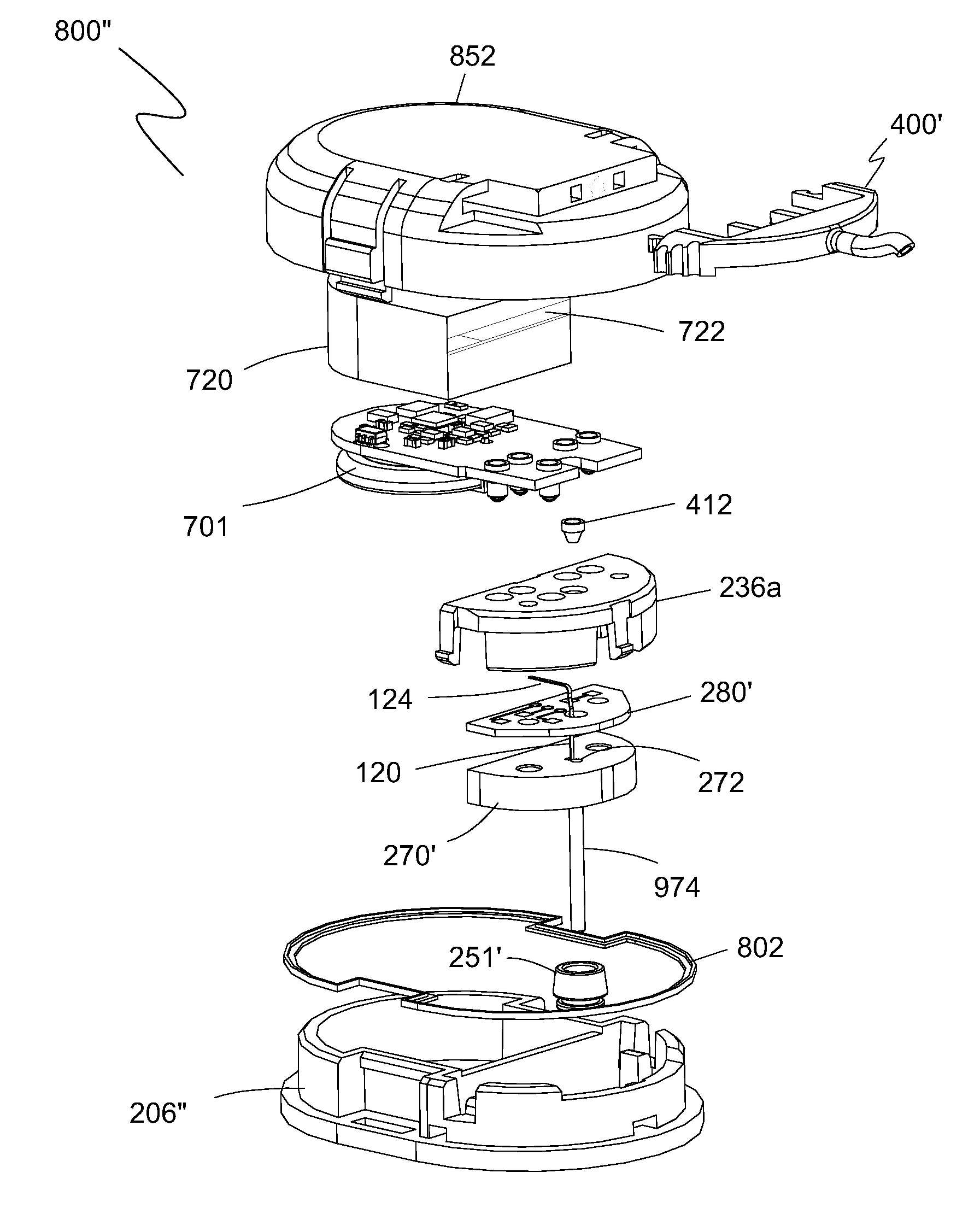
[0124]Exemplary embodiments of the present invention are illustrated in FIGS. 4-54. FIGS. 4 and 5 illustrate perspective views of one embodiment of a sharp 100 of the present invention. Sharp 100 includes a sharp body 102, a sharp open region 104, and a sharp tip 106. Sharp body 102 is an annular section of sharp 100 that extends longitudinally and defines an enclosed conduit 101 therethrough. In one embodiment, sharp 100 is made from 27 gauge XTW stainless tubing having an outside diameter of about 0.016 inch (0.41 mm) nominal and an inside diameter of about 0.012 inch (0.30 mm) nominal. The tubing is then flattened to have an oval or elliptical shape with an outside height 108 along the minor axis of the oval or elliptical shape of about 0.0120 inch (0.30 mm).

[0125]A wire EDM machining operation is used to remove a portion of the tubing wall 103 along sharp 100 a predefined distance to define sharp open region 104, thereby reducing the overall height 110 of sharp 100 along the min...


PUM


Abstract

An inserter assembly for continuous glucose monitoring with medication delivery capability where the assembly has a deployment button containing a needle deployment mechanism having a sharp held in a pre-release position, a housing body in which the deployment button is movably received within a top end of the housing body, the housing body having a sensor deployment assembly containing a lumen and a sensor disposed within the lumen and extending out of the lumen to a circuit board that is part of the sensor deployment assembly, the sensor deployment assembly matingly connected to the sharp where the sharp extends beyond the sensor deployment assembly and contains the sensor not fixedly attached to the sharp, and a sensor housing releasably received within a lower end of the housing body, the sharp extending into a sensor deployment assembly recess within the sensor housing and directly above a sensor opening in a bottom of the sensor housing.

Description

BACKGROUND OF THE INVENTION[0001]1. Field of the Invention[0002]The present invention relates generally to glucose monitoring sensors. More particularly, the present invention relates to glucose monitoring sensors and an inserter assembly therefor for continuous glucose monitoring in a patient.[0003]2. Description of the Prior Art[0004]Lancets are well-known devices commonly used in the medical field to make small punctures in a patient's skin in order to obtain samples of blood. They are utilized in hospitals, other medical facilities, and by private individuals such as diabetics for testing droplets of blood for various analytes. Typically, lancets are used only once in order to reduce the risk of HIV, hepatitis and other blood-borne diseases. The lancet or sharp of these devices is driven into the patient's skin by a small spring that is cocked by a technician or user prior to use. The lancet is covered with a protective, safety cap that keeps the end of the lancet sterile and is...

Claims


Application Information

Patent Timeline
Patent Type & Authority Applications(United States)
IPC IPC(8): A61B17/34A61B5/145A61B5/1473
CPCA61B17/3468A61B5/14532A61B2017/00367A61B2562/04A61B5/1473A61B5/6848A61B5/7405A61B5/14503A61B5/686A61B5/0004A61B5/0031A61M5/158A61B2560/063A61B2560/045A61M2005/1585A61M2005/1587A61B5/1459
Inventor PETERSON, THOMAS, H.CIONEK, SCOTT, P.FLORINDI, ANTHONYHART, JULIAN, I.
Owner SANVITA MEDICAL CORPORATION
Why Eureka
Try Eureka