
Method and apparatus for determining a building location based on a building image

a technology of building location and building details, applied in the field of location determination, can solve the problems of adding errors, limiting building details for matching purposes, and difficult to detect building details,

Active Publication Date: 2016-03-03
RPX CORP
View PDF5 Cites 11 Cited by
  • Summary
  • Abstract
  • Description
  • Claims
  • Application Information

AI Technical Summary

Benefits of technology

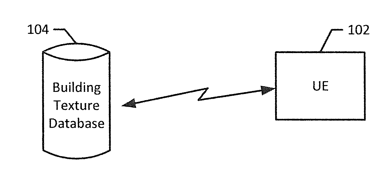
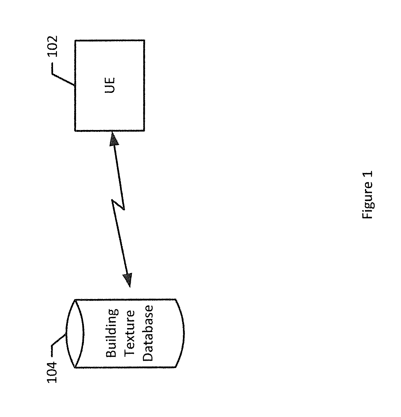
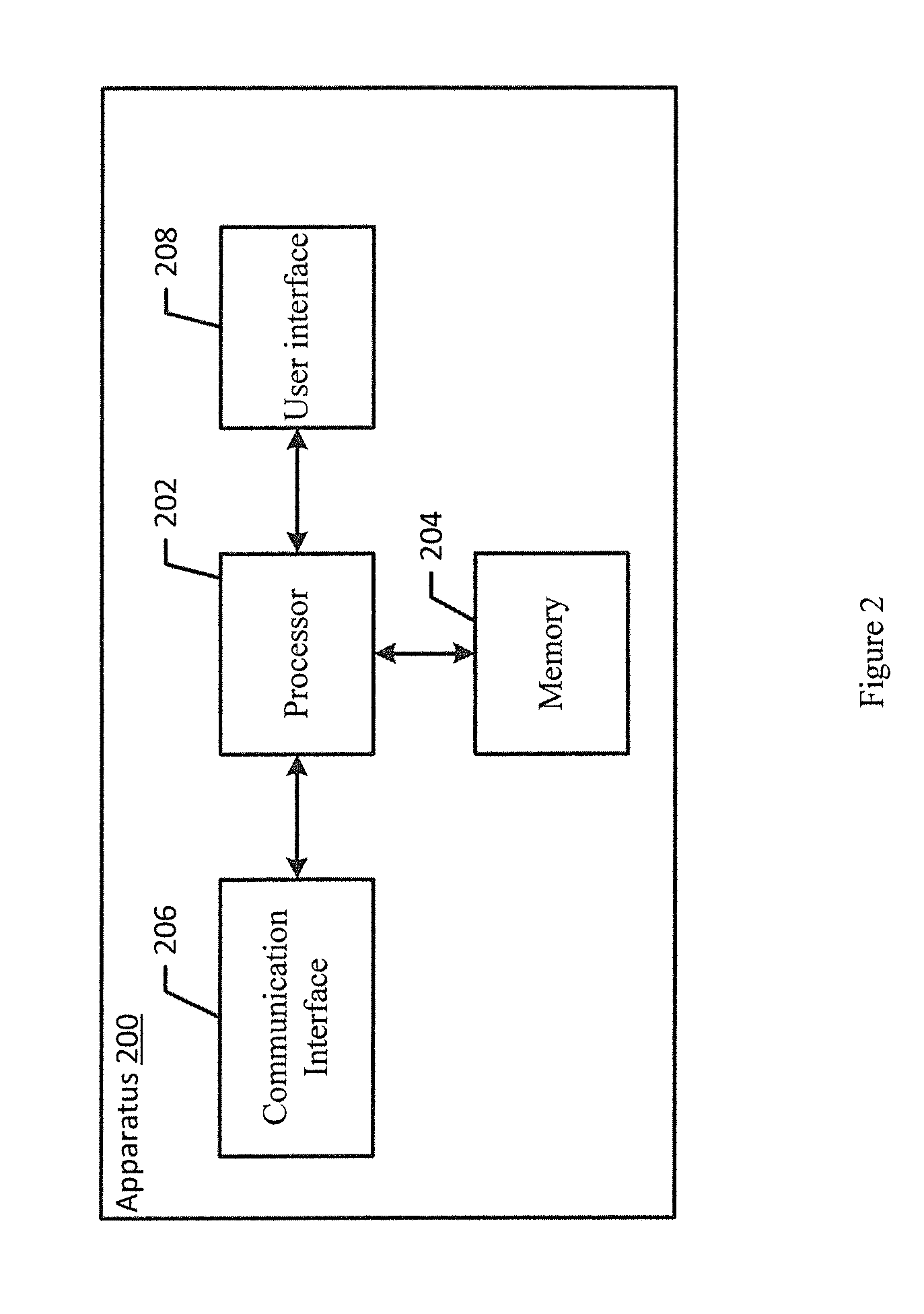
This patent describes a method, apparatus, and computer program product for determining the location of a building based on an image that includes a building. The method involves extracting building texture features from the image and comparing them to reference building texture features that meet a predetermined match threshold. This allows for the accurate identification of the matching building location. The apparatus includes a processor and memory to perform this method. The technical effect of this patent is to provide a reliable and accurate way to identify the location of a building based on its appearance in an image.

Problems solved by technology

These building details may be limiting for matching purposes since there may be a common construction theme or building design used in multiple areas of a city or country.
These building details may also be difficult to detect and may have added error due to camera angle or resolution.
These location systems may return too many results due to the thin matching parameters, or return few or no results due to camera angle or resolution.
Additionally, detailed building features may be difficult to determine and match due to camera position, e.g. angle or focal lengths differing from a reference building image.
It is a tremendous computational and storage burden to store and match each image to all reference images.
Additionally, the match determination may be limited by necessitating the landmark to be predominate in the image.
Further, changes in regions proximate to the landmark may hinder search results as the processed image may not match the background features of the reference image.

Method used


Image

  • Method and apparatus for determining a building location based on a building image
  • Method and apparatus for determining a building location based on a building image
  • Method and apparatus for determining a building location based on a building image

Examples


Embodiment Construction

[0026]Some embodiments of the present invention will now be described more fully hereinafter with reference to the accompanying drawings, in which some, but not all, embodiments of the invention are shown. Indeed, various embodiments of the invention may be embodied in many different forms and should not be construed as limited to the embodiments set forth herein; rather, these embodiments are provided so that this disclosure will satisfy applicable legal requirements. Like reference numerals refer to like elements throughout. As used herein, the terms “data,”“content,”“information,” and similar terms may be used interchangeably to refer to data capable of being transmitted, received and / or stored in accordance with embodiments of the present invention. Thus, use of any such terms should not be taken to limit the spirit and scope of embodiments of the present invention.

[0027]Additionally, as used herein, the term ‘circuitry’ refers to (a) hardware-only circuit implementations (for e...


PUM


Abstract

A method, apparatus and computer program product are provided for determining a building location based on a building image. In the context of a method, the method includes receiving an image including at least one building, extracting building texture features from the image, and receiving reference building texture features. The method also includes determining, using a processor, building texture features comparisons between building texture features and reference building texture features which satisfy a predetermined match threshold and determining a matching building location based upon the building texture features comparision.

Description

TECHNOLOGICAL FIELD[0001]An example embodiment of the present invention relates to location determinations and, more particularly, to a method, apparatus and computer program product for determining a building location based on a building image.BACKGROUND[0002]In some image-based positioning systems, the system may match details of a single building including text on doors or style of entrance. These building details may be limiting for matching purposes since there may be a common construction theme or building design used in multiple areas of a city or country. These building details may also be difficult to detect and may have added error due to camera angle or resolution. These location systems may return too many results due to the thin matching parameters, or return few or no results due to camera angle or resolution. Additionally, detailed building features may be difficult to determine and match due to camera position, e.g. angle or focal lengths differing from a reference b...

Claims


Application Information

Patent Timeline
IPC IPC(8): G06T7/40G06K9/46G06K9/62
CPCG06T7/40G06K9/6202G06K9/4604G06T2207/30184G06T2207/30244G06T7/75G06T7/49G06V20/10G06V10/54
Inventor CHEN, XINZANG, ANDI
Owner RPX CORP
Learn More